Technical Papers
General Tech. Documents
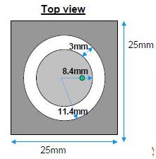
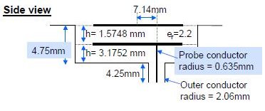
Ultra-wideband Bandpass Filter Using Step-Impedance Resonators(SIR)
Shirish Karveer
This paper presents a compact ultra- wideband (UWB) bandpass filter (BPF) using step- impedance resonators (SIR). The operating frequency range is chosen to fall within the lower UWB spectrum of 3.1 GHz to 10.3 GHz. The passband has a center frequency is 4 GHz. The proposed BPF generates a single passband located at the desired frequency through a single filter circuitry.
The proposed filter is constructed by combination of two highly compact wideband bandpass filters (BPFs) with different physical dimensions which are designed on the basis of a Folded-T-shaped stepped impedance resonator (SIR) and parallel coupling feed structure.
The wideband BPFs can be designed separately, and the design procedure is described. The narrow notched band with 3.8% 3 dB fractional bandwidth (FBW) from 5.15 to 5.35 GHz (IEEE 802.11a lower band) is created in order to eliminate interference from wireless local area network (WLAN) with the determined UWB passband. The center frequency and bandwidth of the notched band can be controlled by tuning the structural parameters. The full-wave EM simulated and measured results are in good agreement, showing that the proposed filter possesses good characteristics including wide passband, high selectivity, low insertion loss, large notch deep and sharp rejection.
A Hybrid Magnetic Field Solver Using a Combined Finite Element/Boundary Element Field Solver (general version published May 2004, Sensors Magazine)
Bruce Klimpke
Magnetic analysis is a key component of motor design. Here’s an explanation of a hybrid finite element/boundary element approach to solve for the magnetic fields involved.
A Hybrid Magnetic Field Solver Using a Combined Finite Element/Boundary Element Field Solver (technical version)
Bruce Klimpke
The dominant method to solve magnetic field problems is the finite element method. It has been used successfully on many devices including motors, solenoids, and actuators. More formally using finite elements is a method of solving Maxwell's equations in differential form.
The less common method of solving magnetic field problems is using the boundary element method. It has been used successfully on many magnetic field problems including sensors, NMR machines, and beam analysis problems. Boundary elements are associated with solving Maxwell's equations in integral form. Both methods have some inherent advantages and disadvantages.
The ideal solution would be to solve a given problem where the advantages of both methods could be applied simultaneously. This paper discusses the advantages of such an approach.
Advantages of NURBS in CAE Modeling
Doug Craigen
Integrated Engineering Software has just completed years of development with the introduction of NURBS replacing the Coons Patch as the basis for the geometric aspect of their modeling. This makes it easier to accurately model general 3D curved surfaces and enables direct links to CAD packages.
Non-destructive Testing using Oersted
J. Dietrich
The purpose of this report is to compare the results of IES’s Oersted software with the analytical results of the impedance of a coil above a two-conductor plane, as given in a publication by Dodd, Deeds and Luquire [1]. Dodd et. al. derives an equation for the impedance based on the vector potential of the coil configuration. Oersted calculates a full-wave solution to the configuration using the boundary element method (BEM). The BEM solves for equivalent sources based on the geometry and the boundary conditions, and then calculates the fields due to these sources. Impedance values are determined from these sources. There is excellent agreement between the results produced by the analytic solution and Oersted.
Boundary Element Method (BEM) for Charged Particle Optics
2001 SPIE Annual Meeting
A. Asi
Boundary element method is used for the purpose of ray tracing of charged particles. The results presented here are based on a commercially available package; Lorentz, by Integrated Engineering Software; a.k.a. Enginia Research Inc. First, a brief description of different numerical methods is presented, followed by some known theoretical examples. In all cases, excellent agreement between the theoretical results and the numerical ones is observed. Several of the examples deal with the space charge issue. Child’s law and Langmuir-Blodgett’s are used to verify these results. Also an example, 743 Test, of launching a particle close to a field discontinuity is presented to show the power of BEM method when it comes to dealing with extreme ratios in the dimensionality within a device
Ion Source Modeling with Lorentz 2D
2001, ION Sources Conference
A. Asi
Lorentz-2D is a boundary element package developed and marketed by Integrated Engineering Software, which can be used for a variety of charged particle optical analysis. In this paper, the program is used in the analysis of two types of Cs+ sputter ion sources. The results are presented and compared versus some earlier empirical and numerical simulations.
Experimental and numerical evaluation of busbar trunking impedance
August 1999, Electric Power Systems Research
Y. Du, J. Burnett, and Z.C. Fu
This paper reports on experimental and numerical evaluation of the impedance of busbar systems with ferromagnetic enclosures (trunking). A linear model is developed in which the ferromagnetic material is approximated by a ‘linear’ material with an ‘equivalent’ relative permeability. The validation of this linear model is carried out through laboratory measurements on a sample system, and a reasonable level of accuracy is demonstrated. With this model, system impedance can be computed by employing the BEM software. The impact of design parameters, such as relative permeability, separation of bars, trunking size, etc on system impedance is discussed. Finally, the impact of these parameters on magnetic shielding is presented for the comparison.
Computer Simulation Scores a Boundary
B.W. Klimpke and A.J. McPhee
As electromagnetic field simulation enters the mainstream of computer-aided engineering, benefits of the technology for pulsed power engineers are emerging. Bruce Klimpke of Integrated Engineering Software and Andrew McPhee of AMS Electronic explain why, and argue the case for the boundary element method.
Integral Equations Revisited
February 1996, ICS Newsletter
B. Trowbridge
It is customary to express a field problem mathematically as either a differential equation or as an integral equation. For example, if a static field solution is required, then either Laplace's differential equation or an integral equation based on Green's theorem are used.
Engineering’s Software Toolbox
October 1995, Engineering Development International
C. Rebizant
Electromagnetic Computer-Aided Engineering gives Electromechanical designers the competitive edge. We examine the flexibility afforded in this field by CAE software.
Superior Solutions for Electromagnetic Field Designs: The Boundary Element Method
As electromagnetic field simulation enters the mainstream of computer-aided engineering (CAE), the boundary element method (BEM) is emerging as the superior solution technique, thereby giving manufacturers a significant competitive advantage.
Comparative Electric Field Calculations and Measurements
April 1992, ELECTRA
R. Parraud
The ability to calculate the electric field strength and potentials on insulators rather than having to perform laboratory experiments would be very helpful. Several computer software packages to perform such calculations based on electrostatic field and applicable to AC are available.
PC-Based BEM Software
June 1990, 19th Annual Symposium on Incremental Motion Control Systems and Devices
Y.B. Yildir
The analysis of electric and magnetic field distributions is imperative for efficient design of increasingly complex electromagnetic devices. In the past, finite difference and finite elements were used for electromagnetic simulation on mainframe and mini computers. The introduction of the boundary element method (BEM) in an easy-to-use field analysis package circumvents the drawbacks of older methods and enables engineers to accurately analyze fields on microcomputers. This paper presents an overview of BEM and its implementation on the PC. The efficacy of BEM is discussed and a design example is presented.
Electric Field and Potential Distributions along Non-Ceramic Insulators with Water Droplets
W. Que and S.A. Sebo
The electric field and potential distributions along wet non-ceramic insulators are calculated using COULOMB, a three-dimensional electric field analysis program. The electric field intensification on the surface of the water droplets on a flat hydrophobic silicone rubber (SIR) sheet is analyzed. The conductivity of the water droplets is also an important factor in the electric field intensification. Under rain or fog conditions, the potential distributions influenced by the water droplets on the weathershed of the insulator are calculated. The plots of equipotential lines for a few typical cases (modeling dry-and-clean, rain, and fog conditions) are also shown.
Electric Field Distribution in Air
W. Que and S.A. Sebo
In this paper, distributions of the electric field and potential in air of two practical cases are presented. The first case is the examination of sphere gaps. The second case is the examination of power line conductors in the vicinity of a tower. Two-dimensional contours of the three-dimensional equipotential and equigradient contours are presented in selected vertical planes. (Gradient here means the potential gradient, i.e., the electric field strength.).
Electric Field and Potential Distributions along Dry and Clean Non-Ceramic Insulators
W. Que and S.A. Sebo
The electric field and potential distributions in the vicinity of non-ceramic insulators under dry and clean conditions are presented. A three-dimensional electric field analysis program, COULOMB, has been used for the calculations. A three-phase 765 kV power line tower geometry is considered for the potential distribution calculations along the insulators. For three-phase energization, two-dimensional contours of the three-dimensional equipotential surfaces are presented in selected vertical planes. The effects of the presence of power line conductors and of the three phase vs. single phase energization on the electric field and potential distributions have been investigated.
Simulation of Non-Linear Devices
T.N. Judge
The Boundary Element Method (BEM) is a well-established numerical method for simulation of physical phenomena including structural, fluid flow and heat transfer analysis. It is particularly interesting in electromagnetics because of its handling of open region problems and its accuracy in computing the fields where gradients are high. Classical BEM, however, does not inherently contain a facility for dealing with regions with inhomogeneous material properties such as those exhibited by realistic magnetic materials. Furthermore, the concept of a reliable and meaningful error calculation is not as well established as it is with the more common Finite Element Method (FEM). This paper outlines a method for handling the effects of material nonlinearity in magnetics problems. A meaningful way of calculating the error in discrete parts of the model is also presented. Finally, the approach is verified through the comparison of results from a commercial BEM package to an analytic case.
Examination of a Design Aid that Simulates Ion Mobility
W.C. Blanchard
This paper presents a comparison of real IMS hardware devices and their actual data with models of these hardware configurations and their simulated ion trajectories. Two conventional IMS devices and an Ion Well IMS device are presented.
Examination of a Design Aid that Simulates Ion Mobility
D. Craigen
One of our benchmark problems for LORENTZ-3D is an axial magnetic field magnetron. This article demonstrates how LORENTZ-3D is able to solve electric and magnetic field solutions simultaneous, then track the trajectories of particles launched in those fields. The field and trajectory calculations are in very close agreement with the analytic solutions, and demonstrate particle trapping as a side-effect of the fringing of the fields in the geometry chosen.
Trajectories in an Axial Magnetic Field Magnetron
D. Craigen
One of our benchmark problems for LORENTZ-3D is an axial magnetic field magnetron. This article demonstrates how LORENTZ-3D is able to solve electric and magnetic field solutions simultaneous, then track the trajectories of particles launched in those fields. The field and trajectory calculations are in very close agreement with the analytic solutions, and demonstrate particle trapping as a side-effect of the fringing of the fields in the geometry chosen.
Symmetry and Periodicity in Models
Integrated Engineering Software Manual
You can create two-dimensional or rotationally symmetric (RS) models. Both of these types reduce a three-dimensional design into a two-dimensional model. The program requires only a cross-section of a model in order to calculate the solution. Modeling the cross-section greatly reduces both the modeling and solution time.
2D Parametric Analysis
Integrated Engineering Software Manual
Parametric analysis is a design-optimization feature that allows you to use variables, rather than static values for specifying design parameters. You define parametric variables by type and by a series of values. You define all parametric variables in the same fashion as the non-parametric variables. Parametric analysis reduces the tedious, repetitive tasks associated with fine-tuning design parameters. For each parametric analysis, you can assign up to 16 variables.
Animation of Parametric Results
Integrated Engineering Software Manual
Parametric analysis of a design allows you to view analysis results for different scenarios involving the model. For example in last months newsletter, we studied the effects of changing the distance between two oppositely charged high voltage cables. We generated results for each step and were able to examine these results. The downside to this is that the images are displayed static for a dynamic analysis.
What if we could display the results with respect to time?
Animation displays an image of the results with respect to time. In the following example, we will analyze and display the results for the field lines generated by a motor. The parametric steps allow us to study the field lines at various positions of the rotor.
Benchmark Challenges
Permanent Magnet Simulation Benchmark (AMPERES benchmark)
Doug Craigen
This benchmark combines a couple of simple well known cases to create a model with an analytic result, yet which is challenging enough to distinguish the relative capabilities of different simulation software for a class of real permanent magnet simulations.
Bar Magnet Benchmarks (AMPERES benchmark)
When evaluating magnetic simulation software you will need some benchmarks for making comparison. Among the benchmarks there should be some of your own measured data on your own products. However, this can be misleading if it is the only benchmark used.
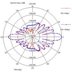
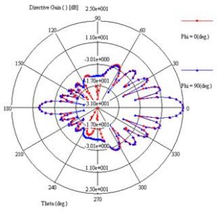
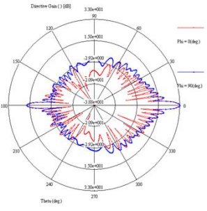
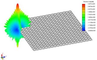
SINGULA: Simulating and analyzing large phased array antennas
SINGULA can simulate large phased array antennas. These can be used for electronic steering of beams. Considering the mutual coupling between any two elements of the array, estimating the radiation characteristics of a large array leads to a very complex model. Using advanced Fast Fourier Transform (FFT) methods, the problem illustrated below was solved.
Benchmark Problem for Simulating Electric Fields Near Sharp Corners
Doug Craigen
One of the most common questions in Electromagnetic simulation is "what/where is the maximum field?". When any kind of corner or edge is present the question becomes tricky. A corner is mathematically a singularity. You cannot ask what is the direction of the field at the corner - that depends on the direction from which you approach it.
Benchmark Problem for Simulating Electric Fields Near Triple Junctions
Doug Craigen
One of the most common questions in Electromagnetic simulation is "what/where is the maximum field?". When a junction is present the question becomes tricky. In the sample case to the left the "triple junction" is a dielectric (left), air (right) and an electrode (bottom). Although the voltage looks well behaved, this junction is mathematically a singularity.
Solving TEAM Workshop Problem 15 With FARADAY
Doug Craigen
We have found that many people with NDE (Non‐Destructive Evaluation) models opt to run TEAM Workshop Problem #15 in FARADAY. This may be to test the reliability of FARADAY on a problem with known results during their free 30 day evaluation, or for some practice when they already own the program. This paper is intended to provide them with some help and educational observations. Thus, this paper doesn't attempt to quantify for you how well FARADAY can solve this particular problem. Rather, it will demonstrate the affect that various decisions about modeling the problem have on the solution time and accuracy in order to teach users how to do this type of problem to whatever level of accuracy they require.
2D/RS Electric Fields
Optimization of Complex Electrode System for Use in Electrical Measurements
Vishnu Lakdawala, Mathew M. Noel, Prathap Basappa and Anusha Jambula
In an attempt to optimize the dimensions of the electrode system for subsequent use in electrical measurements, such as electroluminescence, capacitance and conduction current, field values at key points in an axi‐symmetric electrode system are simulated as a function of clearances between low voltage and guard electrodes. Since the electrode system is axi‐symmetric, a two dimensional BEM solver, has been used for the field simulation. The configurations simulated, results, analyses and configurations for an optimal design are presented.
Benchmark Problems for Simulating Electric Fields Near Sharp Corners
D. Craigen
One of the most common questions in Electromagnetic simulation is "what/where is the maximum field?". When any kind of corner or edge is present the question becomes tricky. A corner is mathematically a singularity. You cannot ask what is the direction of the field at the corner - that depends on the direction from which you approach it.
Electrostatic Analysis of Triggered Spark Gaps
A.J. McPhee, S.J. MacGregor, and S. Turnbull
One of the major considerations associated with the overall performance of a high pressure trigatron is that of lifetime and this becomes particularly important for high repetition rate applications. The problems associated with short trigatron lifetimes are usually related to the erosion of the trigger pin due to successive arcing. Although the erosion per pulse will be dependent upon the specific operating conditions it will eventually lead to an insufficient level of field distortion in the main electrode gas region when triggered, resulting in poor switch performance. In order to maximize the lifetime of a trigatron switch whilst still maintaining good switching performance, an experimental programme was undertaken in which the preliminary design of the trigatron was determined through electrostatic field modelling.
The Design of Dielectric Barriers HVDC Bushings
January 1996, IEE Colloquium on Field Modelling: Applications to High Voltage Power Apparatus
A.G. Sellars and S.J. MacGregor
High voltage bushings employ capacitive grading foils to control the electric field distribution under AC conditions. However, under DC conditions, the foils are unable to prevent a concentration of electric field within the bushing due to its high resistivity relative to that of the surrounding oil. A method of controlling the electric field is therefore required for DC conditions, and this is usually achieved through the use of dielectric barriers which surround the oil-immersed end of the bushing. This paper describes analytical techniques used to assess the performance of a particular barrier configuration in order to optimise its design.
The Repetitive Breakdown and Flashover Properties of Solid Dielectric Mtls. Under DC and Pulse Conditions
A.J. McPhee
Pulsed power engineers have used transformer oil as the high voltage insulator for their transmission line pulse forming networks since work initially began in this area in the 1950's. It exhibits good bulk breakdown properties and can recover its dielectric strength following catastrophic failure, although not as quickly as some gases. However when one of the driving design parameters for a pulsed power system is size, aiming for a compact, high energy density system the use of oil can limit the potential size reductions. Water has also been extensively used in such systems when transmission line length is important and the high relative permittivity can result in length reductions over oil by a factor of 4-5. However when another of the system requirements is high repetition rate the use of water is generally ruled out due to its polar properties leading to conduction under extended repetitive operation.
PC-Based Electrostatic Field Calculation Techniques
May 1991, 12th Annual Ideas in Science and Electronics Exposition/Symposium
S.R. Knutson, M.D. Abdalla, and R.M. Pixton
When working with high voltage equipment, it is helpful to be able to predict what the electrostatic potentials are in the various regions of the equipment during operation. With the development of powerful microcomputers, it has become possible to perform electrostatic calculations of moderate complexity. Though performed at slower speeds than with mainframe computeres, these calculations provide comparable accuracy at a lower cost and with enhanced user interface capabilities. The Personal Computer (PC) based codes evaluated are commercially available and use the Boundary Element Method (BEM) and the Finite Element Method (FEM) to solve electrostatic field problems. These methods use derivative (FEM) and integral (BEM) techniques to solve Poisson's equation for the electrostatic potentials within the region of interest. Both codes allow the user to define the geometry of the problem as well as any dielectric materials with data entry devices (mouse, digitizing table...). The advantages of each method are described and results are shown. These results demonstrate the usefulness of PC-based codes for performing electrostatic analyses.
Calculation of Transmission Line Parameters with the Boundary Element Method
August 1988, ANTEM Conference
Y.B. Yildir and B.W. Klimpke
The objective of this paper is to demonstrate the efficient calculation of design parameters using the boundary element method coupled with a highly interactive package for entering the transmission line configuration. The geometry of the problem that can be solved is arbitrary. Conductors may be infinitesimally thin or may be of finite area. As well, the conductors may be embedded in one or more dielectric materials.
Computer-Aided Field Analysis of High Voltage Apparatus Using the Boundary Element Method
October 1987, International Coil Winding Conference
Y.B. Yildir
The boundary element method (BEM) and its use in computer-aided field analysis is presented. The BEM is compared against the finite difference method (FDM) and finite element method (FEM) for two-dimensional and rotationally symmetric problems. The advantages of BEM are stated for applications in high voltage power apparatus design. It is shown that BEM is superior to FDM and FEM, both for linear and non-linear problems. The recent introduction of the BEM to the microcomputer environment is also discussed.
3D Electric Fields
Electric Field and Voltage Distribution Along Non-Ceramic Insulators
November 2003, INMR World Conference and Exhibition on Insulators, Arresters and Bushings
W. Que and S.A. Sebo
The electric field and voltage distribution (EFVD) in the vicinity of non-ceramic insulators is presented. A three-dimensional electric field analysis program, COULOMB, has been used for the calculations. Computation model development and EFVD results are presented for various examples: dry and clean insulators, 765 kV power line insulators, the effect of water droplets, and insulators under rain and fog conditions.
Electric Field and Potential Distributions along Dry and Clean Non-Ceramic Insulators
October 2001, Electrical Manufacturing and Coil Winding Exposition
W. Que and S.A. Sebo
The electric field and potential distributions in the vicinity of non-ceramic insulators under dry and clean conditions are presented. A three-dimensional electric field analysis program, COULOMB, has been used for the calculations. A three-phase 765 kV power line tower geometry is considered for the potential distribution calculations along the insulators. For three-phase energization, two-dimensional contours of the three-dimensional equipotential surfaces are presented in selected vertical planes. The effects of the presence of power line conductors and of the three phase vs. single phase energization on the electric field and potential distributions have been investigated.
Electric Field and Potential Distributions along Non-Ceramic Insulators with Water Droplets
October 2001, Electrical Manufacturing and Coil Winding Exposition
W. Que and S.A. Sebo
The electric field and potential distributions along wet non-ceramic insulators are calculated using COULOMB, a three-dimensional electric field analysis program. The electric field intensification on the surface of the water droplets on a flat hydrophobic silicone rubber (SIR) sheet is analyzed. The conductivity of the water droplets is also an important factor in the electric field intensification. Under rain or fog conditions, the potential distributions influenced by the water droplets on the weathershed of the insulator are calculated. The plots of equipotential lines for a few typical cases (modeling dry-and-clean, rain, and fog conditions) are also shown.
R2000 Annual Report: Conference on Electrical Insulation and Dielectric Phenomena
W. Que and S.A. Sebo
In this paper, distributions of the electric field and potential in air of two practical cases are presented. The first case is the examination of sphere gaps. The second case is the examination of power line conductors in the vicinity of a tower. Two-dimensional contours of the three-dimensional equipotential and equigradient contours are presented in selected vertical planes. (Gradient here means the potential gradient, i.e., the electric field strength.)
Brittle Fracture Failures at Israel Electric: Study and Analysis
Nov/Dec 2000, Insulator News and Market Report
F. Kaidanov, R.Munteanu, and G.Sheinfain
Between June 1997 and March 1998 four composite insulators failed by brittle fractures on 161 kV lines belonging to Israel Electric. At the time, about 4000 such insulators were already in service on the company's HV lines (beginning from 1989).
Not long before those failures occurred, management at the utility had decided to switch from the use of ceramic long rod insulators to silicone rubber composite insulators for all new 161 and 400 kV lines. In this context, the above successive failures of HV composite insulators in Israel - made many think that the above decision had perhaps been too hasty.
Quadrupole Levitation of Microscopic Dielectric Particles (MEMS)
L.F. Hartley and K.V.I.S. Kaler
Planar quadrupole microelectrodes, fabricated using surface micromachining, have been successfully used to achieve passive levitation of biological cells and other microscopic inorganic particles. To explain certain experimental findings, namely the "size effect", a simple point charge quadrupole model was invoked to explain qualitatively the experimental observations. Subsequently, a more generalized multipolar theory was formulated to handle such higher order multipolar effects. In this paper, we examine the salient properties of a practical planar quadrupole electrode structure as predicted by multipolar theory. The analytical data, obtained from multipolar theory is compared with the numerical modeling results from a boundary element simulation package and the levitation data of microscopic Spheriglass and polymethacrylate particles. The numerical simulation results and the levitation data are both consistent with and in good agreement with the predictions of multipolar theory.
Virtual Prototyping of High Voltage Switchgear
1998, Engineering Development International, FEANI
J. Lopez, C. Rebizant and T. Judge
Developments in CAE have resolved 3-D electrostatic HV Switchgear problems. New computational techniques from Integrated Engineering Software radically change the design process, reducing design cost and development times.
Experience Using the Boundary Element Method in Electrostatic Computations as a Fundamental Tool in High Voltage Switchgear Design
June 1998, IEEE International Symposium on Electrical Insulation
J. Lopez-Roldan, P. Ozers, T. Judge, C. Rebizant, R. Bosch, and J. Munoz
In this paper the Boundary Element Method (BEM) is discussed from an industrial user point of view. First we analyse the advantages of using the BEM specifically for three-dimensional electrostatic computations. Two examples are presented. One model is an epoxy rod between two coaxial electrodes in which the electrical field distribution around metal inserts, H.V. shields and along the creepage distance is required. Also shown is the calculation of the change of field configuration after a discharge between the contacts of a disconnector. In these examples, a three dimensional analysis is necessary because of the geometry of the problem.
Use of the Boundary Element Method for Pulsed Power Electromagnetic Field Designs
June 1997, 11th IEEE International Power Conference
A.J. McPhee
The Boundary Element Method (BEM) is a numerical technique for solving Boundary Integral equations. In this technique electromagnetic phenomena are mathematically described by Maxwell’s equations in integral form. Enforcing the boundary conditions along the material interfaces allows one to obtain a set of boundary integral equations with the unknowns as the equivalent sources or field variables along the interface. One may then separate the boundaries into boundary elements, represent the unknowns on elements, and obtain a system of linear equations. All field variables at any point in space may be obtained by performing integrations associated with the equivalent sources or fields on the boundaries. The BEM is a valuable technique in the electromagnetic field modelling carried out by many engineers during the design phase of their work. The Boundary Element Method has found wide application in fields as diverse as medical, power, defence, research and education engineering design, from the modelling of components (motors, insulators, bushings, lasers etc...) to complete systems, with many pulsed power laboratories and high voltage industries utilising it in various electromagnetic research and development programmes.
3D Electrostatic Modeling of an Extended Lifetime, 100 pps, 500kV, Low Jitter Trigatron
June 1997, 11th IEEE International Power Conference
A.J. McPhee
Two dimensional electrostatic modeling techniques have previously been used to aid the design of a high voltage, low jitter trigatron spark gap. Areas of high Electric field stress could be identified at an early stage of the design process and modified, ensuring optimum performance and lifetime of the spark gap switch. This paper describes the extension of the modelling technique using a three dimensional analysis boundary element method program to design a switch with a predicted lifetime of 106 shots, a single sided jitter of 1ns and an operating voltage of 500kV.
Electric Field Calculations with the Boundary Element Method
February 1993, IEEE Transactions on Electrical Insulation
S.S. Bamji, A.T. Bulinski, and K.M. Prasad
The boundary element method is used to calculate the electric field profiles at needle tips commonly used for electrical treeing tests. Field distributions are also obtained for polyethylene containing a space charge, at the needle tip, and are compared with the values previously obtained by the finite difference method.
Three-Dimensional Electrostatic Field Analysis on the Microcomputer
September 1989, International Coil Winding Conference
Y.B. Yildir
Electromagnetic design parameters can be obtained to a good approximation through two-dimensional modeling of field distributions. Many times the physics of the problem requires three-dimensional analysis. Due to the large amount of data and long modeling and solution times, three-dimensional analysis has been restricted to mainframe, mini and supermicro computers. The application of the boundary element method in an easy-to-use computer-aided field analysis package circumvents the drawbacks of older methods and enables engineers to accurately analyze three-dimensional fields on state-of-the-art microcomputers.
2D/RS Magnetic Fields
Electromagnetic Analysis of Solenoid Coil in IES Software: A Case Study
November 2015, International Journal on Recent and Innovation Trends in Computing and Communication
J.B. Solanki
The aim of this paper is to get theory technical knowledge of designing a electromagnetic solenoid coil and ogy of verifyinginduced current in solenoid coil by using ANSYS Software and IES software. For this purpose a 0.3 T coil has been designed with a Poloidalshaped 1500 turn outer coil of 200 cm diameter. To verify such induced current analysis is a challenging task, theoretically which can be equallycalculated by a FINITE ELEMENT ANALYSIS package and IES (Integrated Engineering Software) , so a same dimension, assembly and has been modeled and meshed in ANSYS 11.0 FEA package and IES (integrated engineering software) with same load data as given in thesoftware. Theoretical and Simulation results have been compared.
A Hybrid Magnetic Field Solver Using a Combined Finite Element/Boundary Element Field Solver
February 2003, UK Magnetics Society
Bruce Klimpke
The dominant method to solve magnetic field problems is the finite element method. It has been used successfully on many devices including motors, solenoids, and actuators. More formally using finite elements is a method of solving Maxwell's equations in differential form.
The less common method of solving magnetic field problems is using the boundary element method. It has been used successfully on many magnetic field problems including sensors, NMR machines, and beam analysis problems. Boundary elements are associated with solving Maxwell's equations in integral form. Both methods have some inherent advantages and disadvantages.
The ideal solution would be to solve a given problem where the advantages of both methods could be applied simultaneously. This paper discusses the advantages of such an approach.
Solenoid and Electromagnetic CAE Tools
July 1996, Engineering Development International
C. Rebizant
The market pressures on electromagnetic system designers to create lower costing competitive designs in shorter design cycles is forcing designers to continually search out better design tools. Electromagnetic CAE (EM-CAE) software tools are good examples of the powerful tools available today for simulating electromagnetic systems such as motors, solenoids, sensors, high voltage systems and other electromagnetic applications. The ability to simulate the performance of a design prior to prototyping can result in significant time and cost savings.
Simulation of Nonlinear Magnetic Devices Using BEM Based Software Tools
T.N. Judge
The Boundary Element Method (BEM) is a well-established numerical method for simulation of physical phenomena including structural, fluid flow and heat transfer analysis. It is particularly interesting in electromagnetics because of its handling of open region problems and its accuracy in computing the fields where gradients are high. Classical BEM, however, does not inherently contain a facility for dealing with regions with inhomogeneous material properties such as those exhibited by realistic magnetic materials. Furthermore, the concept of a reliable and meaningful error calculation is not as well established as it is with the more common Finite Element Method (FEM). This paper outlines a method for handling the effects of material nonlinearity in magnetics problems. A meaningful way of calculating the error in discrete parts of the model is also presented. Finally, the approach is verified through the comparison of results from a commercial BEM package to an analytic case.
Aftermarket Variable Reluctance Sensors
February 1994, Sensors and Actuators Applications, International Congress and Exposition
V.V. Fleet
The purpose of this paper is to enlighten the OE engineer to the work being done by their counterparts in the automotive aftermarket. Specifically, the design methodology used by the author to design variable reluctance (VR) sensors will be described.
Magnetic Analysis of Brushless DC Motors Using the Boundary Element Method
September 1991, PCIM Conference
Y.B. Yildir, B.W. Klimpke, and K.M. Prasad
The advent of high speed microcomputers and available software has made possible the calculation of magnetic fields and torques of brushless DC motors. In particular, the Boundary Element Method (BEM) has shown to be an efficient tool for the design of these motors. This paper explains the BEM approach and addresses the key concerns facing the design engineer using such software, i.e. the ease of use, accuracy of solution, and the computation time required to solve the problem. A sample analysis is illustrated and a torque vs. angle curve is generated for a geometrical configuration to demonstrate the use of the BEM software in the design of brushless DC motors.
BLDC Motor Simulation Using MAGNETO
June 1990, 19th Annual Symposium on Incremental Motion Control Systems and Devices
D.W. Chapman
The magnetostatic characteristics of an 8-pole, 12 slot brushless DC motor were simulated on a model 70 IBM PS/2 with math-coprocessor chip. Version 2.0 of the MAGNETO Magnetic Field Solver two-dimensional, boundary-element method program from Integrated Engineering Software Inc., was used. Non-linear magnetic material properties were used. Results included contour and arrow maps of fields, graphs of normal and tangential fields in the gap, and calculations of torque vs rotor angle, radial forces vs miscentering of rotor to stator, and inductance. The calculated results were in good agreement with experimental results.
Sensorimotor: P.M. Synchronous Motor With Fully Integrated Position Sensor
April 1990, IEEE Intermag Conference
R. Horbor
The magnetostatic characteristics of an 8-pole, 12 slot brushless DC motor were simulated on a model 70 IBM PS/2 with math-coprocessor chip. Version 2.0 of the MAGNETO Magnetic Field Solver two-dimensional, boundary-element method program from Integrated Engineering Software Inc., was used. Non-linear magnetic material properties were used. Results included contour and arrow maps of fields, graphs of normal and tangential fields in the gap, and calculations of torque vs rotor angle, radial forces vs miscentering of rotor to stator, and inductance. The calculated results were in good agreement with experimental results.
Modeling of MIG Heads Using the Boundary Element Method
April 1990, IEEE Intermag Conference
T. Rask, P. Iverson, and J.H. Judy
Mini-Composite Metal-In-Gap (MIG) heads for rigid disks are modeled using the boundary element method (BEM) and compared with a standard ferrite ring head. It is shown that the head field gradient at the writing edge of a MIG head can be approximated by a Karlqvist head at high write currents whereas a saturated ferrite head cannot. It is shown that MIG heads with films having saturation magnetizations of 10kG and 15 kG can write media with maximum coercivities of 1240 and 1800 Oe, respectively. An effective write gap is used to account for the saturation of the C0 core a MIG head at high write currents, and using the Williams-Comstock model, an equation relating head field gradients to the written transition length parameter shows that MIG heads write sharp transitions at high write currents.
An Assessment of Various Magnetic Simulation Tools
June 1989, 18th Annual Symposium on Incremental Motion Control Systems and Devices
W. Cole and H.D. Chai
Not numbered among our objectives is any plan to make dogmatic prescriptions for successful computer modeling. What we seek to achieve in this short paper is the sharing of our modeling experience in a development laboratory whose principal mission is design and manufacture of magnetic devices. But the setting in which magnetic design and development is done varies widely. Such variation must be accounted for when assessing computer modeling tool.
Brushless DC Motors Without Permanent Magnets
June 1989, 18th Annual Symposium on Incremental Motion Control Systems and Devices
J.R. Hendershot
Brushless D.C. motors have received considerable attention throughout the industrial world since the early 1970’s. However their use is still very limited as we approach 1990’s. Computer disc drives and small fans are exclusively D.C. permanent magnet brushless motors. The D.C. servo world is slowly and methodically on an application by application basis being painfully converted to permanent magnet D.C. brushless.
Computer-Aided Magnetic Field Analysis using the Boundary Element Method
October 1988, International Coil Winding Conference
Y.B. Yildir
Efficient design of electromagnetic devices requires the analysis of electric and magnetic field distributions. To this end, the boundary element method (BEM) has been shown to be a powerful technique. This paper presents the use of BEM in computer-aided magnetic field analysis. The advantages of BEM over the finite element method (FEM) are stated. The recent introduction of BEM in a generalized, multi-purpose computer-aided design package is discussed. Emphasis is placed on the ease of use and calculation of design parameters. Modeling and solution of problems which include nonlinear materials and permanent magnets are given.
3D Magnetic Fields
Toward polarized antiprotons: Machine development for spin-filtering experiments
2015, Physical Review Special Topics – Accelerators and Beams
C. Weidemann et al.
The paper describes the commissioning of the experimental equipment and the machine studies required for the first spin-filtering experiment with protons at a beam kinetic energy of 49.3 MeV in COSY. The implementation of a low-β insertion made it possible to achieve beam lifetimes of τb = 8000 s in the presence of a dense polarized hydrogen storage-cell target of areal density dt = (5.5 ± 0.2)X 1013 atoms/cm2. The developed techniques can be directly applied to antiproton machines and allow the determination of the spin-dependent p~p cross sections via spin filtering.
Coupled Effects of Aging and Weak Magnetic Fields on Sequestration of Selenite by Zero-Valent Iron
2014, Environmental Science and Technology
L. Liang, X. Guan, Z. Shi, J. Li, Y. Wu, and P. G. Tratnyek
The sequestration of Se(IV) by zero-valent iron (ZVI) is strongly influenced by the coupled effects of aging ZVI and the presence of a weak magnetic field (WMF). ZVI aged at pH 6.0 with MES as buffer between 6 and 60 h gave nearly constant rates of Se(IV) removal with WMF but with rate constants that are 10- to 100- fold greater than without. XANES analysis showed that applying WMF changes the mechanism of Se(IV) removal by ZVI aged for 6−60 h from adsorption followed by reduction to direct reduction. The strong correlation between Se(IV) removal and Fe2+ release suggests direct reduction of Se(IV) to Se(0) by Fe0, in agreement with the XANES analysis. The numerical simulation of ZVI magnetization revealed that the WMF influence on Se(IV) sequestration is associated mainly with the ferromagnetism of ZVI and the paramagnetism of Fe2+. In the presence of the WMF, the Lorentz force gives rise to convection in the solution, which narrows the diffusion layer, and the field gradient force, which tends to move paramagnetic ions (esp. Fe2+) along the higher field gradient at the ZVI particle surface, thereby inducing nonuniform depassivation and eventually localized corrosion of the ZVI surface.
Open Gradient Magnetic Red Blood Cell Sorter Evaluation on Model Cell Mixtures
2013, IEEE Transactions on Magnetics
Lee R. Moore, Franzisca Nehl, Jenny Dorn, Jeffrey J. Chalmers, and Maciej Zborowski
The emerging applications of biological cell separation to rare circulating tumor cell (CTC) detection and separation from blood rely on efficient methods of red blood cell (RBC) debulking. The two most widely used methods of centrifugation and RBC lysis have been associated with the concomitant significant losses of the cells of interest (such as progenitor cells or circulating tumor cells). Moreover, RBC centrifugation and lysis are not well adapted to the emerging diagnostic applications, relying on microfluidics and micro-scale total analytical systems. Therefore, magnetic RBC separation appears a logical alternative considering the high iron content of the RBC (normal mean 105 fg) as compared to the white blood cell iron content (normal mean 1.6 fg). The typical magnetic forces acting on a RBC are small, however, as compared to typical forces associated with centrifugation or the forces acting on synthetic magnetic nanoparticles used in current magnetic cell separations. This requires a significant effort in designing and fabricating a practical magnetic RBC separator. Applying advanced designs to the low cost, high power permanent magnets currently available, and building on the accumulated knowledge of the immunomagnetic cell separation methods and devices, an open gradient magnetic red blood cell (RBC) sorter was designed, fabricated and tested on label-free cell mixtures, with potential applications to RBC debulking from whole blood samples intended for diagnostic tests.
Magnetron Sputtering of Thin Films
2000, Intevac
R. Kolenkow
Thin films of metals or insulators have a central role in many key technologies, including fabrication of semiconductor chips, computer hard drive memory disks, and high performance optical coatings. "Thin" in this context means films perhaps only 1/1000 the thickness of a human hair - perhaps only a few hundred layers of atoms.
Using CAE Software to Build a New Position Sensor
March 1998, The Journal of Applied Sensing Technology
C. Rebizant and R. Smith
The powerful simulation and prototyping capabilites of CAE software take a lot of the risk out of introducing new sensing technology by reducing development cycles and material requirements and improving sensor performance.
Magnetic Sensitivity of MRI Systems to External Iron: The Design Process
1998, Interface Technology Engineer's Master
N. Campagna and C. Rebizant
The unrivaled combination of speed, accuracy, and ease of use make CAE software that employs the BEM ideally suited for analyses involving shielding of MRI and NMR systems.
The Design of Rotating Magnet Sputter Sources
1998, Intevac VSSD
R. Kolenkow
Thin films - sometimes only fifty to one hundred layers of atoms - play a central role in the fabrication of hard drive memory disks. The required films (typically chromium, magnetic alloy and carbon) are usually deposited by sputtering, where the target material is bombarded by energetic argon ions in a low-pressure plasma discharge, to expel free atoms at the target material.
Using CAE to Design Magnetic Shielding Solutions
1996, Interference Technology Engineers' Master
C. Rebizant and N. Campagna
Thin films - sometimes only fifty to one hundred layers of atoms - play a central role in the fabrication of hard drive memory disks. The required films (typically chromium, magnetic alloy and carbon) are usually deposited by sputtering, where the target material is bombarded by energetic argon ions in a low-pressure plasma discharge, to expel free atoms at the target material.
A Boundary Element Analysis of Team Problem No. 20: Static Force Calculation
November 1993, 4th International TEAM Workshop
K.M. Prasad and K. Davey
Team problem 2D is specially challenging to many field theory codes in that it seeks to determine the force on a highly saturated rod which is centered inside a magnetic yoke. The magnetic fields near the edges of this rod are nearly singular in nature: any attempt to predict the forces using the magnetic fields around the rod, for example, with Maxwell stress tensor, would most likely meet with failure. Most finite element codes approach the calculation of force using the Coulomb energy technique [1], wherein the necessary derivatives on the magnetic field energy are taken inside the variational integrals. The boundary element approach described in this paper seeks yet another alternative for calculating the force. This boundary element approach attempts to represent the field both in the air and in the iron regions with a sheet of current on the air iron interface, with additional volume currents distributed throughout the medium which is saturated. Once the currents are determined, the magnetic field is computed using Biot-Savart and the forces are computed by summing the J cross B contributions.
Summary of Results for Problem 20 (3D Static Force Problem)
1992, Competitive Accuracy Comparison
N. Takahashi
Thirteen computer codes developed by eleven groups are applied to the benchmark problem 20 (3-D static force problem) for the TEAM workshop. The solutions are compared with each other and with experimental results.
Three Dimensional Analysis of Magnetic Fields Using the Boundary Element Method
October 1991, International Coil Winding Conference
Y.B. Yildir, B.W. Klimpke, and K.M. Prasad
Increasingly complex electromagnetic devices require more flexible modelling, and fast and accurate computation of performance parameters. Although two-dimensional analysis provides good approximations, often the physics of the problem requires three-dimensional analysis. Using the Boundary Element Method (BEM) for three-dimensional analysis, now provides unprecedented design opportunities to engineers. This paper outlines the basis of three-dimensional BEM design and analysis of magnetic devices, and contrasts 2D/3D design for optimal utilization of 3D. Options to test solution accuracy are discussed. The torque converter sample problem demonstrates the interactive graphics capabilities,the efficiency and power of BEM in the analysis of magnetic fields.
2D Eddy Currents
Pushing the Limits of 2-D Boundary Element Eddy Current Codes-Connectivity
1996, International Journal of Numerical Modelling: Electronic Networks, Devices and Fields
D. Zheng, K. Davey, R. Zowarka, and S. Pratap
The serious electromechanical designer is faced with optimizing the shape of a device for a number of conflicting criteria. If the design involves eddy currents with saturable media, a true optimization will take a long time, since it requires a lot of information as input with multiple variable variations. If the analyses must be performed in three dimensions, an inordinate amount of computer time is required even for the simplest of problems. No small advantage is accrued if the problem can be approached in two dimensions. The paper outlines a technique for examining eddy currents induced in complex series wound coils for which the connections must be specified to ensure solution accuracy. A boundary element formulation is adopted in which an arbitrary constant vector potential is assigned to each conductor. The connection of the coils can be specified by placing additional constraints on these vector potentials. The technique is tested against two experiments involving forces imposed on flux eliminating coils.
Simulation of Polyphase Induction Machines: Frequency Domain Boundary Element Method
June 1995, International Aegean Conference
Y.B. Yildir and D. Zheng
This paper describes a frequency domain Boundary Element Method (BEM) for simulating and analyzing polyphase induction machines with steady-state sinusoidal time-varying current source excitation. A dual simple-layer boundary integral equation and its numerical solution are presented. Advantages of the BEM technique, such as ease of use, accurate solutions, and significant reduction in computation time, are addressed. A sample analysis is illustrated and some numerical results given for a three-phase induction motor with current excitation to demonstrate the use of BEM software in the design and analysis of the polyphase induction machine. The possibility of analyzing and induction motor with voltage excitation is also outlined.
Handling Velocity Effects with Velocity Dependent Green's Functions: Benchmark Problem No.9
November 1993, 4th International TEAM Workshop
K. Davey and D. Zheng
A boundary element double layer formulation is applied to the problem of a coil moving down a conducting tube. The Green's function for the problem is nonsymmetric having a different value in front of the coil from that behind it. Results of the predicted B fields for v=10 and v=100 m/s are compared to the analytical solution of a coil traveling axially down the center of a conducting tube. Good agreement with the analytic solution is achieved for the field computations.
Towards Function Magnetic Stimulation (FMS) Theory and Experiment
February 1993, IEEE Transactions on Biomedical Engineering
K. Davey, L. Luo, and D. Ross
This paper examines the use of magnetic fields to functionally stimulate peripheral nerves. All electric fields are induced via a changing magnetic field whose flux is entirely confined within a closed magnetic circuit. Induced electric fields are stimulated using a nonlinear boundary element solver. The induced fields are solved using duality theory. The accuracy of these predictions is verified by saline bath experiments. Next the theory is applied to the stimulation of nerves using small, partially occluded ferrite and laminated vanadium permendur cores. Experiments demonstrate the successful stimulation of peripheral nerves in the African bullfrog with 11 mA, 153 mV excitations. These results offer a new vista of possibilities in the area of functional nerve stimulation. Unlike functional electric stimulation (FES), FMS does not involve any half cell reactions, and thus would not have the commensurate restrictions regarding balanced biphasic stimulation, strength duration balances, and oxidation issues, always exercising care that the electrodes remain in the reversible operating regime.
A Computer Program For 2D/RS Eddy Current Problems Based on the Boundary Element Method
September 1992, International Coil Winding Conference
Y.B. Yildir, B.W. Klimpke, and D. Zheng
A computer program, OERSTED, for simulating and analyzing two-dimensional or rotational symmetric eddy current problem with the steady-state sinusoidal time-varying source excitation has been developed at the Integrated Engineering Software (IES). Like other widely used CAE tools developed at IES, OERSTED is a software package based on the most advanced Boundary Element Method (BEM) technique. OERSTED provides a very friendly user interface, exact modelling of boundaries and accurate results. The program has the capability of calculating the skin and proximity effect, resistance and inductance, eddy current, electric and magnetic fields, Joule loss, forces and torques. In this paper, the boundary integral equation formulation and its numerical solution are described. Several application examples are presented to show the accuracy, efficiency and reliability of the program.
3D Eddy Currents
Three-Dimensional Eddy Current Analysis by the Boundary Element Method
March 1996, CEFC
D. Zheng
A boundary element method has been developed for the analysis of 3D eddy current problems. This method is based on the boundary integral equation formulation with equivalent electric and magnetic currents and electric charge as unknowns. Linear shape functions, defined parametrically over a quadrilateral element, have been selected for the Galerkin’s method.
Particle Trajectory
Brightness measurement of an electron impact gas ion source for proton beam writing applications
2016, Review of Scientific Instruments
N. Liu, X. Xu, R. Pang, P. Santhana Raman, A. Khursheed, and J. A. van Kan
We are developing a high brightness nano-aperture electron impact gas ion source, which can create ion beams from a miniature ionization chamber with relatively small virtual source sizes, typically around 100 nm. A prototype source of this kind was designed and successively micro-fabricated using integrated circuit technology. Experiments to measure source brightness were performed inside a field emission scanning electron microscope. The total output current was measured to be between 200 and 300 pA. The highest estimated reduced brightness was found to be comparable to the injecting focused electron beam reduced brightness. This translates into an ion reduced brightness that is significantly better than that of conventional radio frequency ion sources, currently used in single-ended MeV accelerators.
Simulation of Electron Hop Funnels Using Version 9.2 of Lorentz-2E
2014, IEEE Transactions on Plasma Science
T. Rowe, M. Pearlman, J. Browning
Electron hop funnels have been simulated using the new version of the particle trajectory simulation software, Lorentz-2E. Simulations were conducted to determine the validity of the version 9.2 results and the consistency of the results to a previous version of the software, version 8.0. In addition, a new method of injecting a uniform current with all rays of equal charge is discussed, and the results of the method are presented. Version 9.2 of the software was successfully implemented and a new emission model tested. The transition of the software version will allow for faster simulation times of the electron hop funnel simulations to increase the understanding of the device.
Forming of High Current Density Sheet Electron Beams for a SUB-THZ TWT Vacuum Amplifiers
June 2014, Vacuum Electronics Conference, IEEE International
N. A. Bushuev, Y. A. Grigoriev, A. A. Burtsev, I. A. Navrotsky, G. V. Sahajee
In this paper we present the computer analysis of magnetic focusing sheet electron beam with low perveance in the electron-optical systems with an electron gun based on thermionic cathode with a current density of 100 A/cm2 at the distance of tunnel 25 mm.The results of experimental study in the diode mode of impregnated thermionic cathode with linear dimensions 0,1 × 0,7 mm have shown the possibility of using this cathode in sub-THz vacuum amplifier.
Towards smaller gap microbulks
2013, 3rd International Conference on Micro Pattern Gaseous Detectors
D. Attie et al.
Small gap Micromegas detectors (< 50µm) are expected to be optimal for high pressure applications. Combining the microbulk manufacturing technique with a small gap can result in attractive detectors for rare event detection, in particular double beta decay or dark matter searches. We present novel results obtained with small gap microbulks (25 and 12.5 µm) that have been manufactured recently. For the first time for this type of detectors, we show experimentally that for each amplification gap there is an optimal pressure and that smaller gaps are more suitable for higher pressures.
Three-Dimensional Eddy Current Analysis by the Boundary Element Method
June 2004, EIPBN 48th International Conference
V. Ray
Gas Assisted Etching (GAE) and material deposition using gaseous precursors have become a critical part of Integrated Circuit (IC) modification and other applications of Focused Ion Beam (FIB) systems. Widely used methods of gas injection in FIB systems are either needle type or shroud type gas delivery nozzles. Each of these methods of gas delivery has significant drawbacks. Release of the gas from the needle type nozzles detrimental for the vacuum level in main chamber of the system, as the gas quickly dissipates from the process area. Insertion of shroud concentrators into the primary ion beam path the secondary electron path leads to significant decline in S/N ratio of the FIB image. Proposed “CUPOLA” geometry of the gas delivery nozzle would allow to concentrate process gas in the area of interest, as it is currently done by shroud concentrators, and, according to secondary electron trajectory simulations, would significantly improve signal level of secondary electron image, as compared to shroud concentrators.
Boundary Element Method (BEM) for Charged Particle Optics
2001, SPIE Conference
A. Asi
Boundary element method is used for the purpose of ray tracing of charged particles. The results presented here are based on a commercially available package; Lorentz, by Integrated Engineering Software; a.k.a. Enginia Research Inc. First, a brief description of different numerical methods is presented, followed by some known theoretical examples. In all cases, excellent agreement between the theoretical results and the numerical ones is observed. Several of the examples deal with the space charge issue. Child’s law and Langmuir-Blodgett’s are used to verify these results. Also an example, 743 Test, of launching a particle close to a field discontinuity is presented to show the power of BEM method when it comes to dealing with extreme ratios in the dimensionality within a device
ION Source Modeling with Lorentz-2D
2001, ION Sources Conference
A. Asi
Lorentz-2D is a boundary element package developed and marketed by Integrated Engineering Software, which can be used for a variety of charged particle optical analysis. In this paper, the program is used in the analysis of two types of Cs+ sputter ion sources. The results are presented and compared versus some earlier empirical and numerical simulations.
Examination of a Design AID that Simulates ION Mobility
W.C. Blanchard
This paper presents a comparison of real IMS hardware devices and their actual data with models of these hardware configurations and their simulated ion trajectories. Two conventional IMS devices and an Ion Well IMS device are presented.
Single Charge Carrier Type Sensing with a parallel Strip Pseudo-Frisch-grid CdZn Te Semiconductor Radiation Detector
February 1998, University of Michigan
D.S. McGregor and R.A. Rojeski
An improvement in gamma-ray energy resolution is demonstrated for a room-temperature operated CdZnTe semiconductor detector that incorporates a parallel strip pseudo-Frisch-grid detector design. The device construction allows primarily for the measurement of electron charge carriers and not hole charge carriers. The detector is a three-terminal device that requires signal output to only one preamplifier, and its simplistic design offers an alternative method to single charge carrier type sensing to that of coplanar semiconductor gamma-ray detector designs.
Thermal Analysis
Modified Boundary Element Method for Radiative Heat Transfer Analyses in Emitting, Absorbing and Scattering Media
B. Sun and D. Zheng
In this article, an alternative form of Tan's formulation was developed to describe thermal radiation problems in a gray, absorbing, emitting and isotropic scattering medium bounded by a gray and diffusely emitting and reflecting enclosure. The radiosity algorithm was adopted in the governing equations. A modified boundary element method was developed to solve the equations. A group of cases were studied. Numerical results agree well with data available in the literatures which were obtained using other numerical algorithms. The modified boundary element method was found to be effective and accurate in treating general thermal radiation problems. Application of the boundary element method in solving thermal radiation problems is discussed.
Two and Three Dimensional Coupled Electromagnetic/Thermal Analysis for Induction Heating Application Using the BEM
February 1997, 7th International/Induction Heating Seminar
B.W. Klimpke and C. Rebizant
Over the past decade, a new numerical technique has been developed using the boundary element method (integral equations) which lends itself very well to open field electromagnetic and thermal problems. The boundary element method (BEM) approach is gaining recognition within the Induction Heating industry as being an effective and efficient approach to solving industry specific problems. BEM produces precise results with far less data as compared to conventional finite element method (differential equations). BEM caters to open region problems without any artificial truncation of the region and models problem geometries precisely. This makes the BEM approach ideal for solving Induction Heating problems.
Power Systems
Pre-Insertion Resistors in High Voltage Capacitor Bank Switching
October 2004, Western Protective Relay Conference
M. Beanland, T. Speas, and J. Rostron
This paper presents an overview of capacitor switching options and the results of computer simulations for a “typical” application showing the expected transient currents in single-bank and back-to-back switching, as well as the effect of various reactor and pre-insertion resisitor combinations. Results of the simulations are summarized in a table and provide the reader with a simple overview of the results of using pre-insertion resistors in capacitor switching applications.
CAD/CAE Software Aids Converter Design
July 2002, Power Electronics Technology
D. Owsianyk and P. Van Duijsen
Typically, power supply design involves electronic and magnetic components. Using a flyback converter example, let's see how CAD/CAE tools aid the engineer in both areas, reducing prototyping costs and providing insights into system performance.