-
- Actuators
- Coil Design
- Electromagnetic Brakes & Clutches
- Inductors
- Levitators
- MRI
- Motors
- Alternators and Generators
- Electromagnetic Brakes and Clutches
- Sensors
- Loudspeakers
- Magnetic Encoding
- Relays and Contactors
- Solenoids
- Shielding
- Electromagnets
- Magnetic Bearings
- Magnetic Signatures
- Magnetic Fixtures
- Magnets
- Non Destructive Testing
- Particles
-
- Antenna Radiation Characteristics
- Simulation of an Airplane
- EM Simulation of a Desktop
- EM Compatability and EM Interference
- Cable Junctions and Terminations
- Filters
- Lightning Strikes
- Microwave Circuits
- Microwave Ovens
- MRI
- Near Field Analysis
- Radar Cross Sections
- Radio Frequency Cavities
- Reflector Antennas
- Sensors
- Ultra Wideband Antennas
- Waveguides
- Antennas
Transmission Lines
Applications such as high voltage transmission require the analysis of flashover discharges. The insulators that support the high voltage power tansmission lines are associated with complicated conducting structures and corona rings. The simulation of a complete transmitting tower along with power lines – supported by the insulators – is fundamental for the estimation of the electric field levels at an arbitrary point on the insulators and the corona rings.
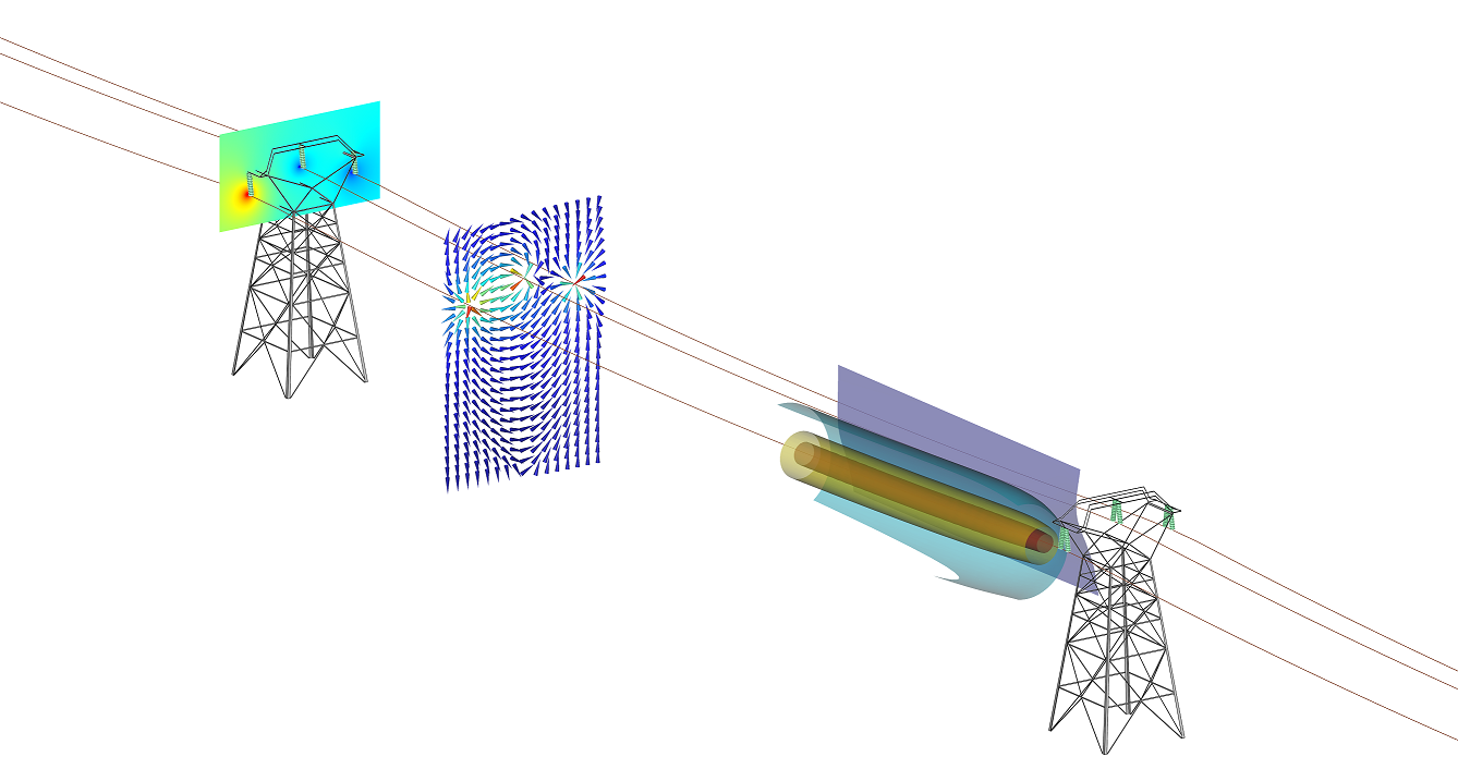
The distance from one tower to the next one is usually about 200 to 300 meters, while its height is 20 to 25 meters. The high voltage transmission runs on power transmission lines with a diameter of about one inch; this size is very small when comparing to the size of the transmitting tower and the distance between the towers.
Modeling the power lines between the towers
The power lines between the towers are long, skinny volumes that complicate the simulation.
This model clearly involves a wide open space around the device, and problems involving such a big open region cannot be simulated using Finite Element Method (FEM). Instead, Boundary Element Method (BEM) is the mathematical solver that better suits the simulation of transmitting towers.
To solve this problem, COULOMB™ incorporates linear segment conductors with the radius of the conductor as an important parameter in the analysis. These linear segment conductors need one-dimensional elements which simplifies the BEM simulation greatly.
In places where tough terrain conditions exist, communication lines run about two meters under the power lines, maximizing the use of the infrastructure built for the power transmission.
The value of the electric field – produced by the power lines at the location of the communication line – must be even lower than an allowable minimum value in order to achieve reliable communication.
COULOMB™ can efficiently simulate these requirements.