Case Studies
Simulation software offers a number of benefits, all of which help limit the need for the construction of actual prototypes. This is achieved by enabling companies to design via computer simulations thereby reducing costs and risks associated with physical prototyping.
Our success stories examine how INTEGRATED’s software dramatically decreases costs and eliminates some of the real-world challenges which companies face when designing devices, components and systems.
Benefits of software modelling in the design and test of transformers
Carlos Carvalho, Director of Technology at EFACEC, discusses the benefits of simulation software for the design and test of transformers.
The EFACEC Group is a leader in the supply of integrated solutions and equipment to the market of power generation, transmission and distribution. The Group forms a complete value chain, from project management to equipment manufacture, where integrated solutions are developed and designed ...
Benefits of software modelling in the design and test of transformers
EFACEC case study
Carlos Carvalho, Director of Technology at EFACEC, discusses the benefits of software modelling in the design and test of transformers
The EFACEC Group is leading the supply of integrated solutions and equipment in the market of power generation, transmission and distribution. The Group forms a complete value chain, from building turnkey projects to equipment manufacture, where integrated solutions are developed and designed in accordance with clients’ needs. The Group offers a comprehensive range of activities such as: Power Generation, Transmission and Distribution, Automation and Telecontrol Systems, Electric Mobility Power Supply Systems as well as Maintenance and Technical Assistance Services.
The director of Technology, Carlos Carvalho, leads a 120 - strong Engineering team in the EFACEC Power Transformers business unit: “Our division has the capability to design and manufacture Core and Shell type power transformers up to 1500 MVA, 525 kV, mobile substations up to 90 MVA, immersed and dry type distribution transformers. As such, a core element of EFACEC’s business is the design and manufacture of power transformers. In the current market, transformers need to be ever more effective and competitively priced. To do this, we at EFACEC employ simulation software to build virtual prototypes of the system prior to manufacture, to avoid wasting time on costly mistakes.”
He continues, “For the past 26 years EFACEC has been using simulation software from INTEGRATED Engineering Software to help iron out any design issues in the early stages, before they prolong the design lifecycle. The software we use at EFACEC are the ELECTRO, COULOMB, FARADAY and INDUCTO products. ELECTRO is a 2D/RS electric field solver designed specifically for applications such as transformers. ELECTRO can calculate electric field strength, transmission line parameters and capacitance. Our designers can automatically vary and experiment with geometry, materials and sources, therefore reducing the tedious, repetitive task of fine–tuning multiple design parameters. COULOMB is, by contrast, a 3D electric field solver used for calculations such as electric field strength, transmission line parameters and capacitance. Finally, FARADAY is a 3D eddy current field solver which can calculate force, torque, displacement current, flux linkage, induced voltage, power and impedance.”
Despite using software simulation, a yet unsolved problem in the design of transformers came to light. The weak link theory was adapted to the design of the insulating structures inside oil immersed power transformers. The stratified insulation media is composed by pressboard barriers and oil channels. The dielectric permittivity of the pressboard is twice that of the oil and so the electric field accumulates in the oil channels. The oil dielectric strength is also much lower than that of the pressboard, so, in theory, if you can guarantee the dielectric strength of the weak oil, then the whole insulating structure will withstand the electric stress.
This empirical knowledge was developed initially by some power transformer manufacturers, and later, became public knowledge through technical papers published by Weidmann, a major supplier of pressboard to the power transformer industry. Weidmann carried out several research experiments to settle the oil-curves, a group of decaying exponential E-field strength versus length curves that are accepted as almost the standard in the transformer industry.
Carlos continues, “We at EFACEC came across this theory and requested that INTEGRATED develop it into a software solution for inclusion in its programmes. INTEGRATED wrote a programme which was capable of this feature, effectively turning theory into reality.” In less than a month, EFACEC had a custom-made solution to its problem, known as the partial discharge (PD) inception dialog feature.
“The Partial Inception dialog feature helps us in our modelling and design phase by enabling us to simulate the dielectric tests and to evaluate the dielectric strength of the insulating structures between the windings, the leads, the bushing tails and the tank turrets etc. In the power transformer industry we can say that each transformer produced is unique, therefore during the design phase, each transformer is like a prototype and so there are constantly new challenges to analyse”, says Jacomo.
There are many other applications for which the PD inception analysis may be useful, as it does not impose the base and the exponent of exponential oil curves. Therefore, users can replace these oil curves with their own air curves, silicon curves, tangential to porcelain curves or similar. Carlos concludes, “We at EFACEC strongly advocate the use of modeling software to test designs as it cuts costs and supplies real flexibility, particularly where a product range comprises of major elements, large transformers in this case, which are always slightly different from the last one manufactured. Even with our very specialised applications we have been able to achieve all the capabilities we require from software simulation.”
For more information about EFACEC and INTEGRATED, please visit:
http://www.efacec.pt/PresentationLayer/efacec_competencias_00.aspx?idioma=2&area=2
For more information, contact us here
13 years later, FEI still appreciates the advantages of the Boundary Element Method for particle trajectory
FEI is a leading diversified scientific instruments company, featuring electron and ion-beam microscopes and other instruments for nanoscale applications across many industries: industrial and academic materials research, life sciences, semiconductors, data storage, natural resources and more. With a 60-year history of technological innovation and leadership, FEI has set the performance standard in transmission electron microscopes ...
13 years later, FEI still appreciates the advantages of the Boundary Element Method for particle trajectory
FEI case study
FEI is a leading diversified scientific instruments company, featuring electron and ion-beam microscopes and other instruments for nanoscale applications across many industries: industrial and academic materials research, life sciences, semiconductors, data storage, natural resources and more. With a 60-year history of technological innovation and leadership, FEI has set the performance standard in transmission electron microscopes (TEM), scanning electron microscopes (SEM) and DualBeams (tm), which combine a SEM with a focused ion beam (FIB). FEI's imaging systems provide 3D characterization, analysis and modification/prototyping with resolutions down to the sub-Angstrom (one-tenth of a nanometer) level. FEI’s standard line of products and custom-designed instruments can be found in laboratories around the world.
Jim McGinn, a Staff Scientist with FEI, has dedicated over three decades of work in the electron optics field, and he joined FEI 22 years ago. It was in 1999 that FEI bought the first package of LORENTZ, INTEGRATED’s beam optics and charge particle trajectory design analysis tool. Today, FEI still relies on LORENTZ for testing and modeling during the design process.
The FEI Beam Technology team appreciates many of the technical capabilities in the software package. One key feature McGinn enjoys is the Boundary Element Method (BEM), a solver developed by INTEGRATED. “The Boundary Element Method is more computationally efficient than the Finite Element Method (FEM) and it also enables us to better define complex surfaces than the Finite Element Method (FEM). From our viewpoint, the Boundary Element Method makes it very quick and easy to set up a problem,” says McGinn.
Another highlight for McGinn is the CAD import capability of LORENTZ, because it “makes it very quick and easy to create a model. Of the various electromagnetic codes that we have, and we have many, LORENTZ is the only one that offers a full CAD import, and that makes it very useful.”
FEI was able to use the magnetics portion of LORENTZ to get very good results. McGinn finds the magnetic analysis tools in LORENTZ are relatively easier and more straightforward to use than the other code they use for magnetics. The magnetics work that McGinn is able to do in LORENTZ, because of the way that the user interface is created for defining magnetic sources, is very useful. He adds, “The way that the electric boundary conditions are defined inside of Lorentz in the user interface is extremely useful, quick and easy.”
“I just wanted to make sure that everybody understands how much we appreciate the work that Bruce (Klimpke, INTEGRATED’s Technical Director) and his group have been doing on the improvements to the code,” McGinn concludes, “and we are excited about the new steps that are happening in the upcoming version of LORENTZ. We’re very much looking forward in continuing to work with INTEGRATED in the development of future releases.”
“It’s my pleasure to get to work with INTEGRATED. We all here at FEI are really excited about the good new movement that you are making with the software, and we are appreciative of that.”
For more information, contact us here
CAE Software speeds up development in the design of modulators and sensors
Photonic Systems, Inc. (PSI) offers comprehensive microwave photonics engineering and manufacturing capabilities. With decades of collective photonics experience, PSI is a recognized leader, bringing best-in-class component and link solutions to customers in defense, communications, research and government. Their products enable a broad range of system performance...
CAE Software speeds up development in the design of modulators and sensors
Photonic Systems case study
Photonic Systems, Inc. (PSI) offers comprehensive microwave photonics engineering and manufacturing capabilities. With decades of collective photonics experience, PSI is a recognized leader, bringing best-in-class component and link solutions to customers in defense, communications, research and government. Their products enable a broad range of system performance, from basic transmission of RF over fiber for antenna remoting, to complex signal processing in radio astronomy or defense applications. Component products -such as low Vπ LiNbO3 modulators, high current photodetectors and high accuracy component controllers- are offered as integrated link products, operating to bandwidths beyond 40 GHz with the highest spur-free dynamic range and lowest noise figure available.
PSI performs research on a variety of fibre optics projects, many of them for the US Defense Department, which includes the development of new electro-optic modulators.
Courtesy of Dr. Gary Betts, Photonic Systems, Inc.
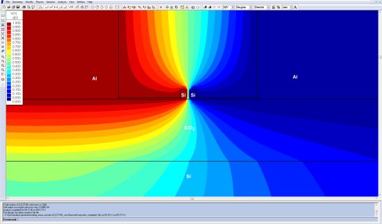
As an engineer with PSI, Dr. Gary Betts uses ELECTRO for the electromagnetic analysis and design of electro-optic modulators. ELECTRO is the 2D/RS field simulator from INTEGRATED Engineering Software chosen by Dr. Betts to model the device and calculate the electric fields and microwave properties of the electrode within the modulator. The electric field in the modulator turns the light on and off, so it is very important to have an accurate model of the electric field produced by the electrodes.
In terms of the specific application, most modulators are used to communicate signals over a fiber-optic communication network. Dr. Betts explains that there are other applications where the modulator is used to sense voltages or electric fields; in these applications the device is called a “field sensor” or a “voltage sensor,” but it is still the same basic device.
Dr. Betts has extensive experience in the modulator field. The fibre optics field was all research up until the middle 80s. At the beginning in the 90’s, modulators were basically a research device; over time some models have been commercialized. Dr. Betts started with research while he was at the Massachusetts Institute of Technology (MIT) in the 90s, and then it was 2002 when he joined a private company bringing with him years in research.
Dr. Betts remembers that 20 years ago, before he had ELECTRO, he would have to do approximate solutions, build the device, measure it and see if it worked. Over time, PSI has used two different design methods: one is ELECTRO and the other involves a kind-of-homemade finite element solution. Even though the accuracy is probably similar, ELECTRO is much easier to operate and use because it’s all graphical and the user can “just type in points and see what happens. The ease of use is much better than the alternative”, Dr. Betts remarks.
Dr. Betts bought his first copy of ELECTRO in the mid 90’s, before he joined PSI. Today, Dr. Betts is still using this software to solve, in some sense, the same problems that he used to solve back then: the details are different but the general application is the same. Dr. Betts comments, “I think I bought it three or four times over the years, and one of those packages had become my personal copy”.
With ELECTRO, Dr. Betts has extensive experience and confidence; the software does everything he needs well so there was never a need for him to look at any other software package. As PSI has gotten involved in more difficult microwave problems, they bought a 3D high frequency microwave simulator which can calculate some of the same things ELECTRO does. “But what I found was”, Dr. Betts explains, “that because the other software package was trying to do all of these complicated problems, it did a very poor job at calculating 2D electrical fields. For the application we have we needed to know the fields very accurately. I ended up still using ELECTRO for when I needed to know the fields of the TEM mode, and I only used the other software for parts of the problem where I needed particular types of microwave solutions such as reflections from a coaxial launcher or modal properties of the dielectric substrate, for example.”
“With ELECTRO I can calculate pretty accurately what is going to happen the first time I build the device: it is likely to either work exactly right or only need one re-design. ELECTRO vastly reduced the amount of money we had to spend on trial and error applications: the development cost is much less when we have good modeling software”, Dr. Betts concludes.
For more information, contact us here
3D Design of Ion Implanter Sub-Systems
Nissin Ion Equipment USA Inc., is the technology leader in the development of cluster ion implantation sub-systems and advanced ion source materials for the manufacture of logic and memory chips. Nissin's technologies enable the utilization of cluster beam ion implantation for manufacturing the world's most advanced integrated circuits at the lowest cost and highest throughput ...
3D Design of Ion Implanter Sub-Systems
Nissin Ion Equipment case study
Sami Hahto, Chief Scientist at Nissin Ion Equipment USA Inc, discusses the benefits of using LORENTZ software in the design of ion implanters.
Nissin Ion Equipment USA Inc (formerly SemEquip), is the technology leader in the development of cluster ion implantation sub-systems and advanced ion source materials for the manufacture of logic and memory chips. Nissin Ion Equipment's technologies enable the utilization of cluster beam ion implantation for manufacturing the world's most advanced integrated circuits at the lowest cost and highest throughput. Ion implantation is a crucial step to dope silicon semiconductor wafers at various stages of integrated circuit fabrication.
Dr. Sami Hahto, Chief Scientist at Nissin Ion Equipment USA, uses LORENTZ for all aspects of designing the systems. LORENTZ is one of INTEGRATED’s most popular simulation tools, already recognized for providing fast and accurate results, modeling of boundaries and easy analysis of open region problems.
Nissin Ion Equipment develops subsystems for ion implanters: starting from the creation of the ion source, they design the front end of the implanter consisting of the ion source, beam extraction systems and also beam line components like mass analyzer magnets, electrostatic lens elements and quadrupole magnets.
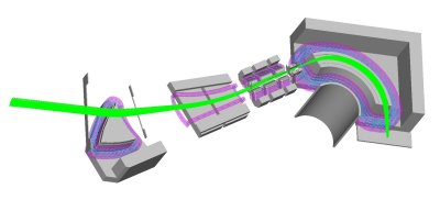
courtesy of Dr. Sami Hahto, Nissin Ion Equipment USA Inc
LORENTZ allows Hahto a detailed analysis starting from the source, which is the first component in the system. In general, plasma sources are used, either RF or ECR (electron cyclotron resonance) or discharge sources. Nissin Ion Equipment has developed what is called “electron-impact” source. This type of source is needed since they use materials that are heavy clusters (cluster molecules which have up to 40 atoms in one cluster, instead of one or two), making them very fragile. Ionization is very delicate so they use electron beams. Electron beam is emitted from an electron gun, and shot around a 90 degree bend into a source ionization chamber where it ionizes the clusters.
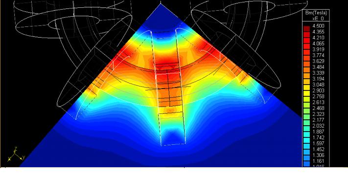
In the source alone, Nissin Ion Equipment has two permanent magnet circuits that are independent. Both are very important: one is part of the electron beam formation and bending; the other one is for plasma confinement. Both circuits are designed with LORENTZ, and always have been. “We have had great success,” Hahto comments. “We have designed several generations in the last six years using mostly 3D LORENTZ. Our fairly complicated permanent magnet circuits and electrostatic electron extraction optics need to precisely focus, secure and trap the electron beams and plasma.”
The company has designed the whole electron gun - the first part of their system - using LORENTZ. That includes the magnetic, electric and charged particle/electron beam modeling. Solidworks is the CAD package used for drafting the designs and then they are very seamlessly imported into LORENTZ. Once modeling, Hahto mostly does all the changes in Solidworks, defines the models in LORENTZ and then runs them. Hahto explains: “It’s been very successful for us, prototyping and productization. We do one prototype and then we productize with minor modifications. LORENTZ is so precise that we do not need multiple prototypes and we can cut a lot of development cycle time. In the past, before the software was there, it would have taken much longer.”
When comparing LORENTZ with other particle trajectory analysis software packages, Hahto annotates that INTEGRATED’s package is much more seamless in terms of user interface, more graphical, easier to learn, but also the importing of the CAD data is a key feature. “What I love about LORENTZ,” he continues, “is the surface meshing, basically the boundary element adaptability: that’s the big advantage. You can actually model things that are much larger in reasonable time. You can have precision where you need it. The automatic meshing is very good, but I actually prefer doing my own meshing most of the time. If you know how to do that, you can select the meshing to have the precision only where you need. It can speed up the models a great deal compared to the finite elements in other software packages. That’s where the differences are most evident.”
As mentioned above, Hahto also designs electrostatic ion extraction systems, which form the ion beam. This process involves designing electrostatic structures that are biased to high voltage and pull out the ions from the ion source and form and focus the ion beam injecting it into rest of the beam line. That ties into one important part of their system: high voltage insulators. Nissin Ion Equipment has large - 100 kilovolt - insulator bushings, isolated from ground, that hold the whole ion source and the front assembly. They use LORENTZ for designing the devices. Hahto has used 2D but mostly the 3D version, achieving very good results. “We had an older design that was done basically semiempirically before I joined the company,” Hahto comments. “Then, in the last two years we used LORENTZ to design these new insulators, looking into triple point stress shielding and surface fields, and we had quite good success.”
Nissin Ion Equipment faced another complex ion optical problem that they solved using LORENTZ; they managed to increase the beam currents of the lowest energy ion beams by almost a factor of ten by designing decel lens in the beam line to decelerate and focus the ion beam to the semiconductor wafer. LORENTZ’s capability to accurately model charged particle beam space charge was critical for this development.
Hahto has also used LORENTZ in the past for projects related to negative ion extraction systems for fusion research and accelerator applications like medical isotope production. Neutron generators are another area where Hahto has utilized LORENTZ. These are basically generators that use 100KV deuterium or tritium beams shooting on titanium targets and creating neutrons for cargo screening or other similar applications.
For more information, contact us here
NASA Goddard’s Cryogenics branch benefits from new engineering software
NASA satellites and spacecraft require fairly advanced temperature control which ensures that the electronic components and highly sensitive instruments work properly. Every piece of equipment has a temperature range in which it works properly. The equipment may be damaged if it gets too far outside its operating temperature range. Much of NASA’s equipment (both in space and on the ground) is designed to work at room temperature...
NASA Goddard’s Cryogenics branch benefits from new engineering software
NASA Goddard case study
Brent Warner, Aerospace Engineer at NASA, discusses the benefits of modeling in the design of cooling systems for satellites and spacecraft.
NASA satellites and spacecraft require fairly advanced temperature control which ensures that the electronic components and highly sensitive instruments work properly. Every piece of equipment has a temperature range in which it works properly. The equipment may be damaged if it gets too far outside its operating temperature range. Much of NASA’s equipment (both in space and on the ground) is designed to work at room temperature. However, some equipment, including some of the sensors used to make astronomical observations, must be cooled to cryogenic temperatures to have the necessary sensitivity.
Some of the systems used to cool those sensors are built by NASA Goddard’s Cryogenics Branch. The coldest systems that the group designs combine a bath of liquid helium, at slightly above 1 kelvin (that is, slightly above 1 degree above absolute zero) with an Adiabatic Demagnetization Refrigerator (ADR), which takes the temperature down to less than 0.1 kelvin.
At atmospheric pressure, liquid helium boils at 4.2 kelvin. At lower pressures, liquid helium boils at lower temperatures. The lowering of boiling point with lower pressure is normal for liquids; cooks know that water boils at a significantly lower temperature at high altitudes than it does near sea level. Similarly, a liquid helium bath can be cooled to around 1 kelvin by reducing the pressure above it. In the laboratory, a vacuum pump lowers the pressure. In space, the surrounding vacuum does the job.
The ADR produces its cooling by the action of a changing magnetic field on a block of a paramagnetic (that is, weakly magnetic) substance. The properties of each substance determine its useful temperature range. Unfortunately, no single substance has a range that stretches from room temperature down to the coldest temperatures that the Goddard cryogenics group must achieve. This explains why the group’s flight ADRs are combined with a bath of liquid helium, which connects to the ‘hot’ end of the ADR.
Although the changing magnetic field is a necessary part of the ADR, the field can create problems if it penetrates other parts of the spacecraft, especially the very sensors that the ADR is intended to cool. The sensors are designed to respond to the faintest of incoming signals. Such sensors may therefore respond also to disturbances arising from other equipment in the spacecraft, including the magnetic field of the ADR. Therefore, the cryogenics group designs shielding to ensure that the magnetic field outside the ADR will be below the limits required for proper operation of the rest of the spacecraft.
The critical cooling of instruments
Although much of NASA's equipment operates at room temperature, some needs to be cooled to cryogenic temperatures. For example, telescopes which study the skies in the infrared. Infrared light has wavelengths longer than visible light. It is often called "heat rays," because warm objects (including room temperature objects) radiate in the infrared. Obviously, a telescope designed to study infrared light should not be radiating in those wavelengths.
Given the obvious connection between cooling and infrared, it may come as a surprise that the Goddard cryogenics group developed its first satellite ADR with a helium system for an x-ray instrument, the X-Ray Spectrometer (XRS). There are two ways that the cooling helped the XRS achieve its desired sensitivity: by reducing noise in the electronics and by taking advantage of the properties of the materials used to construct the sensor.
Heat is a random motion of atoms, molecules and electrons. These random motions in the wires, and the other components, cause random noise in the electric currents that make up the signal. By cooling the electronics, many of the random motions that cause noise are eliminated. Thus allowing the instrument to accurately record and measure weaker signals.
The XRS uses microelectronic sensors, constructed by the same methods used for integrated circuits. When an x-ray hits a sensor, the energy of the ray is absorbed, warming the sensor slightly. The amount of warming indicates the energy (and hence wavelength) of the x-ray. The materials properties are such that, the colder the sensor, the greater the temperature change for a given energy input. The greater the temperature change, the easier it is to measure.
Modelling of equipment
To allow NASA Goddard’s Cryogenics branch to develop equipment which can operate at room temperature and at extremely low temperatures while minimising magnetic field leakage, the Aerospace Engineers rely extensively on using engineering software to model, refine and identify improvements before beginning the manufacturing process.
The Cryogenics branch recently switched to using 2D and 3D magnetic field solvers from modelling specialist INTEGRATED Engineering Software. This software enables them to model the magnetic field and shielding requirements of any cooling system.
Brent Warner, Aerospace Engineer within Goddard’s Cryogenics group at NASA, designs cooling systems for satellites. Brent commented, “One of the difficulties of magnetic design is that we often need to know the size of the field in areas where it would be difficult to measure directly. Because the basic physics of magnetic fields is well known, we're confident that we can get accurate values from the software in those areas.”
NASA has been using software from INTEGRATED since 1992, while Goddard’s Cryogenics branch at NASA started to use it in 2001. Previously it used the Poisson group programs. Brent continues, “These programs are free, but not as easy to use. They use a text file for data input, which was state of the art at the time the codes were first written. In contrast, INTEGRATED’s programs have a more contemporary graphical user interface for data input and manipulation.”
Brent continued, “In Poisson, to enter the details of the model, you have to type a text file, which lists all of the characteristics. You list the entire X, Y co-ordinates of all of the pieces that you are studying and include a list of the magnetic properties, such as iron or other magnetic materials that you are using. With Magneto for example, you just draw a picture on the screen, you can still type in all of the coordinates, but the picture is visible.”
MAGNETO and AMPERES calculate not only the magnetic fields from understood structures such as coils or solenoids, but also the magnetic field caused by other materials and unusual structures that are much more difficult to calculate.
Raise Shields
It is also possible to calculate the field of a coil using general mathematical software, assuming that the equations are known. However, that software will not calculate the field when magnetic material such as iron, is added to the model. The solution depends on the magnetic properties of the iron (which are nonlinear) and on the shapes of the iron pieces and their positions in the field generated by the coil. This additional complexity is precisely what specialised magnetic software is designed to accommodate.
Bruce Klimpke, Technical Director at INTEGRATED explained, “With MAGNETO and AMPERES, the user can easily fill in the details of the outline of the shape of the shield, and run the program to see what the results are. This allows engineers or designers to efficiently work out a complex calculation, and quickly change the details, such as one material to another material, or change the thickness or the shape.”
The software enables the user to look at magnetic material, such as the iron being used to create a shield, and identify whether it has been saturated. If the field is too high and it can’t provide any more shielding, this would indicate that the user might need to increase the thickness of the shield material. The shield needs to be as thin as possible, because the apparatus that is being designed to go into space needs to be as light as possible.
Boundary Element Analysis
MAGNETO and AMPERES provide multiple options for the display of results. Brent comments; “This is an advantage because you can quickly switch between displays and study various quantities once the program has calculated the answer.”
The previous Poisson tools, could calculate the magnetic field in a given area – but if the user needed to find out the magnetic field outside that area, they had to input the data, set the problem up and run it all over again. This can be a time consuming process. MAGNETO and AMPERES includes the Boundary Element Method as one of the field solvers in the software package. The user only needs to increase the calculation area and the programme will work out the field readings itself.
Brent commented, “To do the sort of job that we are doing, we need advanced and easy to use software. Both the 2D and 3D software that we use with a graphical user interface helps us get our job done much quicker.”
Brent continues, “This image demonstrates a plot of the magnetic field. I have set the lower limit to display the field at a level of 50 Gauss. (You can see that in the View Range input section.) Where the field is below 50 Gauss, the window background shows through. If I were required to keep the field outside of our cooler below 50 Gauss, then setting that display limit would let me quickly see where I have met that requirement and where I have not.”
“This graphic shows the magnetization which the response of the magnetic material to the field created by the coil. It is the response of the material that creates the shielding effect. Every material has a maximum magnetization, so its useful to know if the design approaches that value. The magnetization in the ends of the shield is much lower than in the middle. This suggests that we could save weight and space by using thinner end caps. That's the sort of design decision you could make by studying a display of the magnetization.”
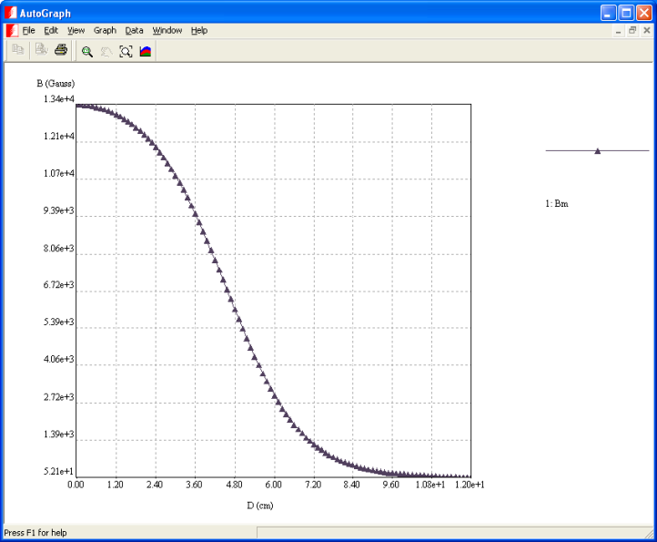
Brent further explains, “This graphic shows a graph of the B field along the axis, from the center, out to a point 12 cm away from the center. MAGNETO created this graph when I set it to display the graph along a segment, then clicked on the line that's in the left side of all the other pictures. In MAGNETO, if there is a place where you know ahead of time that you will want to see a graph of some quantity, you can draw the line while you're drawing the model. Then, when you have the model solved, you can simply tell the display section to create a graph along a segment, click on the segment, and you've got your graph.”
The systems in the above pictures are not finished designs. They represent the early stages in the design process. Usually, the requirements that go into a design include:
- A limit on the "fringing fields", which is the magnetic field in areas outside the cooler. The limit is because other equipment is sensitive to the magnetic fields.
- A specification on the field strength inside the coil at the location of the "salt pill", which is shorthand for the block of paramagnetic substance.
- A weight limit, in the case of coolers that will fly in a satellite. If the original design is too heavy, the designer needs to identify places where the shield can be reduced.
Brent adds, “In designing a shielding system, I'd probably go back and forth with the user of the system 15 or so times, adjusting various dimensions to get things right. All of the design decisions affect other design elements. For example, the shield affects the field in the center of the coil. So, if you were originally planning on running the magnet with a particular current to get a particular field, then when you add the shield, you would need to decrease the current in the coil to drop the field back to the size you want. But, when you drop the current to the magnet, that would decrease the field everywhere, including the fringing fields. So you might not need as thick a shield.”
Bruce Klimpke concludes, “Engineering software is hugely beneficial to designers. It allows engineers such as Brent Warner to model equipment to extremely specific and sensitive specifications, without actually having to physically build anything, thus saving significant time and money. This is particularly important in the current economic climate, where organizations are tightening their belts.”
For more information, contact us here
Siemens relies on ELECTRO for its everyday transformer engineering
Siemens AG’s Energy Sector, particularly its Division “Power Transmission” uses Electro , an electric field simulator from Integrated Engineering Software, as an every-day tool to assist in transformer design and test.
All over the world transformers are used in systems for transmission of electrical energy from power-plants to consumers. Siemens AG offers...
Siemens relies on ELECTRO for its everyday transformer engineering
Siemens case study
Dr. Beriz Bakija, Power transmission technology & innovation engineer at Siemens, discusses the benefits of modelling in the design and test of transformers
Siemens AG’s Energy Sector, particularly its Division “Power Transmission” uses ELECTRO, an electric field simulator from Integrated Engineering Software, as an every-day tool to assist in transformer design and test.
All over the world transformers are used in systems for transmission of electrical energy from power-plants to consumers. Siemens AG offers tailored solutions which it develops and manufactures in the form of high- and medium-voltage switchgear, transformers, substations, energy automation for power supply networks and service infrastructures.
Modelling transformers for high-voltage power transmission is a complex task. The transformer types differ. Each insulation system has different dimensions and the operational voltage covers a wide range.
Siemens delivers systems which include transformers up to 1200 kV and Ultra high voltage transformers for UHVDC transmission systems up to 800 kV.
Dr. Beriz Bakija supports specialists at the related departments of the Siemens Energy Business Unit “Transformers”. “We develop insulation systems together with the experts in all Siemens transformer manufacturing plants worldwide.” He continues, “We push related innovation activities to provide latest product technology. These activities support the goal to be quality leader in the transformer industry.” The technology and innovation team drives product and production related innovation activities for the Business Unit “Transformers” worldwide.
“For our purposes, “ELECTRO” is actually the preferred software tool for every-day engineering. It is important to have software that is very quick and easy to learn and this product is more than capable of handling the large models we require.” Some years ago Siemens standardised “ELECTRO” as a design tool for everyday calculation of electrostatic or quasi-static field calculations for the design of its transformers. After that the worldwide use by the company has been implemented so that every design in general could be checked by using “ELECTRO”. “There’s no day that I don’t open Electro at some stage to work on a transformer design”, says Dr. Bakija.
“Normally we use Electro for 2D calculation - focussing on rotational symmetry - because the insulation systems are all generally symmetrical. Sometimes deeper investigations need to be done and then we model those aspects separately using other 2D calculations in Electro.”
As it is a fairly specialized product, Siemens makes use of essential capabilities provided by “Electro” and has been involved in continuous improvement process of the software in association with Integrated.
“We have an excellent relationship” Dr. Bakija continues
Siemens has a long experience in modelling to test designs as it cuts costs and supplies real flexibility, particularly where a product range comprises of major elements, large transformers in this case, which are always slightly different from the last one manufactured.
For more information, contact us here
German scientific institute uses simulation software for range of testing
IFW Dresden, a Scientific Institute based in Dresden that focuses on solid state physics and materials science research, has been using INTEGRATED Engineering Software’s AMPERES modeling software for advancing some major projects it is working on.
Formally known as The Leibniz Institute for Solid State and Materials Research Dresden, IFW Dresden is a non-university research institute...
German scientific institute uses simulation software for range of testing
IFW Dresden case study
IFW Dresden, a Scientific Institute based in Dresden that focuses on solid state physics and materials science research, has been using INTEGRATED Engineering Software’s AMPERES modeling software for advancing some major projects it is working on.
Formally known as The Leibniz Institute for Solid State and Materials Research Dresden, IFW Dresden is a non-university research institute. It is concerned with modern materials science and combines explorative research in physics, chemistry and materials science with technological development of new materials and products. Its main research program is focused on functional materials which hold a key position in many fields of application: superconducting and magnetic materials, thin film systems and nanostructures as well as crystalline and amorphous materials.
The Institute has been using INTEGRATED Engineering Software’s 3D simulation program AMPERES for over five years now and initially acquired the software specifically to aid in the calculation of superconducting magnetic bearings and its applicability for superconduction trains. Using the software for three dimensional simulations, the stray field distribution above the magnetic track is optimised so that levitation forces are maximized acting on the superconducting vehicle. AMPERES is also used for testing both the magnetic switch for optimal use and the calculation of forces that act between the magnetic blocks which are used to build up the magnetic track. IFW has been so pleased with the results using the software that in 2009 they invested in the revised version and it is now used by many teams in the Institute.
IFW Dresden also promotes the work of young scientists and the training of technical staff and one area that the trainees are working on with AMPERES 3D modelling is the Magnetic Force Microscope (MFM). The software is used to calculate the stray field distributions of very tiny magnetic tips with different distances away from the tip, performing quantitative MFM. Until now it has only been possible to take qualitative images but with the aid of these simulations they are able to work towards quantative evaluation of the measured signals. In particular they are modelling pyramidal shaped MFM tips and calculating their stray field distributions.
The AMPERES modeling software is also used for work on a magneto optical microscope. For this it is essential to test and optimize the stray field geometry of in-plane magnets to create the best values of strength and homogentity of magnetic fields in order to study the behaviour of magnetic domains in magnetic fields.
The team working on the Electro Chemistry project, where the corrosion process of magnetic material is under investigation, also used AMPERES. Magnetic fields can affect electro chemical corrosion in aqueous electrolytes and they normally localize and enhance the corrosion process. During the corrosion process of ferromagnetic metals the geometry parameters and the resulting flux density distribution in front of the electrodes can be important. So the team needs to simulate the strength the magnetic forces induced and, therefore, establish how they influence the corrosion process. They simulate the whole experimental set up, optimize it, and achieve high gradients of flux density or, in other cases, to avoid it.
IFW Dresden was founded in 1992, originally part of one of the largest and well renowned materials science centres in the former GDR. It employs about 400 people, among them 190 scientists, mostly physicists, chemists and materials engineers. 80 of them are young scientists working in the IFW on their doctoral thesis. About 100 guest scientists from all over the world come every year to work at the IFW.
For more information, contact us here
Electric field calculations are essential for high voltage insulators
Occurrence of water droplets due to environmental conditions on outdoor high voltage (HV) insulators can lead to localized field enhancement, causing partial discharges and dry arcs which can ultimately result in complete flashover. The reason for this study was to explore the effect of contact angle of water droplets on electrical stress intensification and its implications...
Electric field calculations are essential for high voltage insulators
Norfolk State University case study
By Prathap Basappa of Norfolk State University, Virginia, USA.
Occurrence of water droplets due to environmental conditions on outdoor high voltage (HV) insulators can lead to localized field enhancement, causing partial discharges and dry arcs which can ultimately result in complete flashover. The reason for this study was to explore the effect of contact angle of water droplets on electrical stress intensification and its implications. Delivering power from a generating station and delivering it to the end customer – whether a consumer or a business- is a complicated process. Ultimately a power grid is as good as its weakest link. A major part of the grid is designing and creating insulators that reduce the likelihood of failure due to flashovers.
These insulators provide isolation between HV power lines and the grounded structures and need to be able to survive the extremities of electrical and mechanical stresses in order to achieve a better longevity. There are two types of insulators present in the market today, Ceramic and Non-Ceramic or Polymer Insulators. Polymer insulators, which were introduced in the 1970’s, are increasingly being used due to their characteristics such as better hydrophobicity, light, weight and ease in handling. However, ageing through deterioration is unavoidable since the polymer insulators are made up of organic materials.
When exposed to certain environments, such as pollution, wet conditions, acid rain and ultraviolet radiation, the ageing of the polymer insulator speeds up. Whilst pollution is of little significance under dry conditions, the presence of water droplets enhances the electric field intensity, which causes the droplets to become deformed and elongate in the direction of the electric field. This results in a shortening of the insulating distance, causing a leakage path on the insulator surface. Development of arcs takes place, and ultimately results in complete flashover. Hydrophobicity is affected by this phenomenon, decreasing the lifetime of the insulator. Even under relatively moderate applied voltages, the enhanced stresses occur at triple points of solid, gas and conductor interfaces and initiates partial discharges. Photons and ions produced by the discharges may lead to secondary electron emission and other discharge processes along the solid and trigger flashover, if the stress is sufficiently large.
To increase the longevity of the insulator a study has been undertaken of the behaviour of water droplets on the insulator in presence of electric field. This was done using a 3D Boundary Element package from INTEGRATED Engineering Software. The COULOMB modelling software is a 3D electric field solver used for applications such as power transmission lines, transformers, insulators, bushings and grounding electrodes. Its calculations include electric field strength, force, torque and capacitance and designers can automatically vary and experiment with geometry, materials and sources.
The team worked on two scenarios. The first was the hydrophobic case where water droplets reside as discrete droplets on Silicon Rubber (SIR). The second case is when water droplets coalesce and form a film due to the diminution of the hydrophobic property. The first set of simulations inquired the role of single, multiple discrete water droplets on the shed and the sheath region in enhancing the E-Field. The second set of simulations looked into effect of the water films on the shed region. A high voltage insulator (138KV) made of SIR is considered to perform the electric field calculations.
In the flashover mechanism, the electric field at the high voltage end, the water drops/films bridging the sheds as well as the shanks play a crucial role. Flashover can occur even if the surface away from the energized end is not fully wetted. The probability of an arc initiating and bridging the insulator is largely governed by the maximum electric stress that occurs on the insulator surface as well as the percentage of the insulator length where the stress exceeds the streamer threshold stress. The presence of a hydrophobic coating (for example: RTV coating) inhibits the formation of water films, leading to formation of discrete water particles which are less dangerous.
Previous studies included simulations using a simple insulator and studying the electric field variations with respect to the water droplet’s contact angle, position and the material of the insulator used. The other set of simulations focuses on the behaviour of the water droplets on a practical High Voltage insulator of 138KV and a water droplet of a 90° contact angle is considered. The water droplets were placed on the shed and the sheath regions of the HV insulator and then the number of water droplets was increased to three with the same placing. When the insulator gradually looses the property of hydrophobicity, the contact angle progressively reduces leading to formation of water films instead of droplets. The effect of water films on field intensification was studied by placing water films on the insulator surface. Six cases were considered using a water bubble with a diameter 4mm with a contact angle of 90°. The relative dielectric constant of water was taken as 80 and a conductivity of 2.0e-4 mho/meter.
From the results obtained from the simulations the team concluded that the electric field is at the maximum when three water droplets exist on both shed and the sheath regions and it is minimum when single water droplets exist on the shed region of the insulator. The streamer breakdown voltage is exceeded in all the cases, with half more prone to the occurrence of flashover. The sheath part of the insulator has a narrower dimension when compared to the shed region, which means it experiences a higher amount of stress. On the sheath region, the water droplets will deform into an ellipsoidal shape that leads to greater enhancement of the electric field. Simulation showed that along the sheath, the direction of stress concentration is tangential to insulator surface, explaining why the stress concentration occurs at the triple point between insulator, water and air. In the case of water droplet on the shed the electric field is perpendicular to the shed. Because of this the electric field is enhanced at the top of the drop away from the insulating material comprising the shed. This means that the corona initiation, and subsequent flashover, occurs at the sheath region and the field distribution in the shed region may not significantly affect the conditions. In reality there are often many water droplets on the insulator and each drop would have an effect on the electric field and on each other.
The first set of results show that water droplets in the sheath region greatly contribute towards enhancing the probability of initiation and progression of wet flashover on the insulator surface. The second set of simulations revealed that the electric field intensification is more when there is abatement of hydrophobic property on the SIR insulators when compared to the discrete droplets case. The team concluded that on application of higher voltages the percentage of the length of the insulator, where the field exceeds the streamer threshold, voltage also increases as well as in locations where the voltage spikes (implying locations where the flashover can probably start) occur. Reduction or absence of hydrophobicity leads to formation of water films but when hydrophobicity is increased by RTV coating the possibility of water films forming is drastically reduced. The water films are broken up into discrete particles and, although the voltage spikes are increased in number, the stresses at the initial water droplets end, close to the HV, only exceed the streamer threshold voltages.
Using software for modelling and simulation made all the difference to the work required for this study as it would involve writing several thousands of lines of code, debugging and implementing complex surfaces and interfaces Much of the modelling work was undertaken by students, under the guidance of a junior and senior professor, and they all found the simulation programmes easy to use with good back-up and assistance from INTEGRATED Engineering Software. Apart from its ease of use, one benefit the team found using COULOMB was that they were able to create complicated geometries and obtain usable results in a relatively short amount of time. In the past solutions were pure guesswork and the results could never be exact. Now the calculations are done within the software reducing the need to play around with coding. One can concentrate more on analysing the results and producing useful practical conclusions instead of incessantly debugging and creating meaning out of numbers which may not be accurate.
For more information, contact us here
University of Nottingham designs artificial heart at 5% of the current cost
There are 11.2 million sufferers of Congestive Heart Failure (CHF) worldwide, which is steadily increasing by 10% annually. Each year, 3000 people receive a heart transplant as the only current long-term treatment for CHF. Blood pumps offer a solution either as a bridge to transplantation or to recovery. The market potential is valued at $5.4 billion annually...
University of Nottingham designs artificial heart at 5% of the current cost
University of Nottingham case study
There are 11.2 million sufferers of Congestive Heart Failure (CHF) worldwide, which is steadily increasing by 10% annually. Each year, 3000 people receive a heart transplant as the only current long-term treatment for CHF. Blood pumps offer a solution either as a bridge to transplantation or to recovery. The market potential is valued at $5.4 billion annually.
However, since the current cost of manufacturing the complex parts that are needed in modern artificial hearts is around $30,000, the availability of the device is severely limited.
In a recent study conducted by Andrew Hilton at the University of Nottingham, it was found that a few changes to the current design of centrifugal blood pumps reduced the total cost to 5% of the original cost by designing around standard stock parts that are currently available from engineering suppliers.
Under the current design of blood pumps, the pump must operate continuously pumping at 6 litres/minute, cycling at a rate between 2,000 -20,000 revolutions/minute. The pump must have an operating temperature under 37° Celsius and provide energy sufficient energy on a beat-by-beat basis to replicate the pressures seen within the heart.
The system must be nontoxic to the human body, damage to cellular components, and element s such as platelets must be prevented. The system must not produce blood clots (thrombi) that can lead to a malfunction of the pump and ultimately a stroke.
For the new design of pump, Hilton optimized his model by using AMPERES (from INTEGRATED Engineering Software), a CAE software package designed to perform full three-dimensional simulations of magnetic physical systems. The geometry was designed for a pump operating at 2000 rpm. Full specifications included inlet and outlet diameters, blade heights at each inlet and outlet and the appropriate casing size that enabled the designer to maintain a constant velocity of the fluid. The new drive system employed the use of electromagnetic coils to drive the pump. There was only one moving part in the whole system, no mechanical seals around rotating components, and a full non-contact bearing that minimizes heat generation and maximizes the reliability of the design.
In the design of the drive system various arrangements of magnets were considered. Primarily, the magnets had to be small enough to fit inside the impeller. This has direct consequence on the attractive force seen between the two components. Secondly, the angular orientation of the magnets produces a significant radial force maintaining the central axis of rotation of the impeller. By using off-the-shelf components, such as pre-sized permanent magnets and stock electromagnets, it is possible to construct a drive system similar to that seen in the VentrAssist device.
The drive system was designed by evaluating the forces that occur within a blood pump, such as shock forces due to the patient falling over. The appropriate magnet configuration was selected, and has been modeled using computational analysis. It was necessary to measure how the force of attraction between the parts varied at angles of misalignment; this was modeled using finite element method/boundary element method (BEM) using AMPERES. The program provides users with a wide variety of analysis options, including the ability to create contour plots and graphs of field quantities. To perform a simulation in AMPERES, a geometric model of the physical system was constructed, by using the built-in geometric modeler.
Once the geometric model was built, physical properties such as material and magnet flux density vector orientation were assigned. The BEM analysis yielded results for the axial force and the torque between the components at angles of misalignment, and showed how the coupling may be used as a radial bearing by examining how the radial forces vary with an increasing cone angle.
The research found that the total cost of the pump is reduced by implementing a drive system that acts as a magnetic bearing; it consists of two components: permanent magnets with the impeller of the pump and the electromagnets within the pump casing. Using stock components available from standard engineering suppliers, the cost of manufacturing may be reduced up to 95%. An upcoming prototype incorporates a hybrid electromagnetic drive/bearing system, together with a hydrodynamic bearing.
For more information, contact us here
Design of high voltage systems for pulsed power technology
BAE Systems is a global company engaged in the development, delivery and support of advanced defence, security and aerospace systems in the air, on land and at sea. The company designs, manufactures and supports military aircraft, combat vehicles, surface ships, submarines, radar, avionics, communications, electronics and guided weapon systems. It is a pioneer in this technology with a heritage stretching back hundreds of years...
Design of high voltage systems for pulsed power technology
BAE Systems case study
BAE Systems is a global company engaged in the development, delivery and support of advanced defence, security and aerospace systems in the air, on land and at sea. The company designs, manufactures and supports military aircraft, combat vehicles, surface ships, submarines, radar, avionics, communications, electronics and guided weapon systems. It is a pioneer in this technology with a heritage stretching back hundreds of years. It is at the forefront of innovation, working to develop the next generation of intelligent defence systems. BAE Systems has major operations across five continents, with customers and partners in more than 100 countries.
The Electromagnetic Technology Group is based in Bristol at the BAE Systems Advanced Technology Centre, which is renowned for its cutting edge research in a variety of technology areas. The EM Tech group specialises in designing high voltage systems for pulsed power technology – where energy is accumulated relatively slowly and then released very quickly.
Dr. Peter Leask, a Principal Scientist at BAE Systems, has been using INTEGRATED Engineering Software for over five years, especially ELECTRO (2D/RS). This is an easy-to-use electric field solver for applications such as arresters, cables, transformers, high voltage shielding, insulators and bushings. It is fast and accurate at calculating electric field strength, force, torque, transmission line parameters and capacitance. With ELECTRO designers can automatically vary and experiment with geometry, materials and sources cutting out some of the tedious and repetitive tasks that comes with the fine–tuning of multiple design parameters.
“In terms of IES’s software library, we use ELECTRO 95 percent of the time and we have found it a very easy program to get to grips with. It is quick to model and cost effective. Typically the devices that we model using ELECTRO are high voltage electronic components such as switches and transformers. Because of the cutting edge nature of our work it is essential to use modelling software at the beginning of the design process. From time to time we also use INTEGRATED’s COULOMB for 3D modelling, though this is a minor part of our operation.”
Particularly useful to BAE Systems has been the option to solve electrical rotationally symmetric (RS) problems, which give a realistic solution at an early stage, eliminating the need for many costly rounds of prototyping. ELECTRO’s links to major CAD packages also prove useful, true representation of complex geometric shapes means that files are directly transferable, eliminating the need to re-draw designs for CAD. Using the program it is easy to draw a concept for a new piece, analyse field stresses or capacitance on an iterative basis and then modify the design within the program.
COULOMB is a 3D electric field solver that can be used for designing applications like high voltage shielding, cables, transmission lines and printed circuit boards. Its calculations include electric field strength, transmission line parameters and capacitance.
As with all design processing, the use of INTEGRATED’s software varies, one week it may not be used at all and the next week every day. At BAE Systems it is primarily used in the early developmental stages of a product, enabling the designer to prove the concept before physical prototyping begins. “This helps alleviate any issues before we get to the, usually expensive, prototype stage” continues Leask. “The measurement functions help us to monitor the electrical stress in the designs and keep it below critical levels. The software allows us to keep iterating until we are happy with the level reached in all the regions of the model. Then we build the prototype. We have six people trained to use this modelling software and most weeks there is someone working with it for at least four or five hours.”
The designs that Leask’s team work on often involve metal components that have very different applied voltages. They use ELECTRO to ensure that these parts are kept the correct distance apart so that the intervening insulating material does not breakdown during use. Given the nature of the product under design, the team is often working with strange shapes and find ELECTRO useful in assessing the capacitance in these situations. “Before using this modelling software it was very much ‘back of envelope’ calculations and ELECTRO has really speeded up the process and increased accuracy at an early stage,” Leask added.
“The major benefit to BAE Systems of using INTEGRATED Engineering Software for our modelling is that we are able to test the design in ELECTRO and then export that information directly to CAD. From there we can create the final model without having to do any redrawing at all. This gives us great time and cost savings at every stage of the process,” concludes Leask.
For more information, contact us here
Analyzing Faraday isolators in sophisticated optical systems
Qioptiq is a global manufacturer of sophisticated optical systems. The company is a pioneer in the field of photonics - one of the central growth markets of the 21st century. Its core business includes the development and production of customer-specific sub-systems and integrated system solutions which meet stringent technological demands. The company's product range focuses on Information Technology & Communications, Health Care
Analyzing Faraday isolators in sophisticated optical systems
Qioptiq case study
Qioptiq is a global manufacturer of sophisticated optical systems. The company is a pioneer in the field of photonics - one of the central growth markets of the 21st century. Its core business includes the development and production of customer-specific sub-systems and integrated system solutions which meet stringent technological demands. The company's product range focuses on Information Technology & Communications, Health Care & Life Sciences and Industrial Manufacturing markets.
Kristiane Gans, an engineer in research and development at Qioptiq’ BU Laser Technology, is based in Munich where the company uses INTEGRATED Engineering Software when modeling its designs. “Qioptiq has been using AMPERES for six years, though I have only been working with it for the past three since I transferred to doing this research.”
AMPERES is an easy-to-use 3D magnetic field solver for applications such as clutches, solenoids, sensors, actuators, MRI and magnetic shielding. Fast and accurate, it can calculate force, torque, flux linkage and inductance. Its powerful parametric solvers allow designers to automatically vary and experiment with geometry, materials and sources, reducing the tedious and repetitive task of fine–tuning multiple design parameters.
Gans is working on Faraday isolators that are situated at the front of lasers. These ensure that the reflection back off the surface of elements in the optical path do not confuse the laser itself. “Our customers are mainly producers that use our products to develop lasers which cover a wide range of uses from medical to visual.
Faraday isolators are optical components which allow light to travel in only one direction and the mode of operation is based on the non-linear Faraday effect (magneto rotation). In principle, the function of an optical isolator is analogous to that of an electrical diode. The isolators are composed of three elements; the entrance polarizer, the faraday rotator and the exit polarizer.
Thin film polarizers are commonly used as entrance and exit polarizers, typically in form of a special polarizing beam splitter cube, and have an extremely high extinction ratio. Designed for use with high power lasers, the key element of the Faraday isolator is the Faraday rotator which consists of a strong permanent magnet containing a crystal with a high Verdet constant.
Light of any polarization entering the entrance polarizer exits as horizontally or vertically linearly polarized light. Since laser light is usually linearly polarized, one can match the orientation of the entrance polarizer and the laser by simply rotating the isolator. Light then passes through the Faraday rotator. For most wavelengths the crystal is a Terbium Gallium Garnet (TGG) crystal which is placed in a strong homogeneous magnetic field. The crystal length and the magnetic field strength are adjusted so that the light polarization is rotated by 45° on exiting the crystal.
The maximum isolation of the Faraday isolator is limited by the inhomogenities of the TGG crystal and the magnetic field. However, it is possible to square the extinction ratio by placing two isolators in series and by arranging the polarity of the two magnets to be opposite to each other. This way the polarization direction of the transmitted light remains unchanged in the transmission direction and the effect of both magnetic fields is enhanced, which leads to a more compact isolator. The strength of this effect depends on the distance between the two magnets and can be used to tune the isolator to different wavelengths. The adjustment is necessary because the rotational angle of the TGG crystal is wavelength and temperature dependent.
This is what we have been developing at BU Laser Technology since the early 1990s,” continues Gans. “Before we started to use AMPERES it was just a case of trial and error but since we have had the software we are able to calculate the mechanistic skills of the components. We only work with cylindrical magnets so the laser beam is always inside the magnetic field. We need to know just how strong the magnetic field is at any given point and it is very interesting to see what will really happen. The magnetic field is not homogeneous, it is different at different places, and we need to have this information.
“Working with AMPERES has lead to a more straight-forward product development process because it is no longer based on guesswork. We now know in advance what we can expect at the end. We can change the parameters of the geometry and can see straight away the effect that we will get by changing for example the diameter or length. I often use the parametric mode to analyze trends in the design.”
Gans has been on a visit to the INTEGRATED Engineering Software workshop in Winnipeg. “It was really great and I found it so useful. The visit helped me to better understand the software and learn about some of its capabilities that I was not aware of prior to the visit. One thing that I learnt about was the parametric run which now plays a very important role in the processes I use,” adds Gans. “Another thing they taught me was how to import a model from CAD. It was really good to know that you can import all the stuff that you constructed in CAD so that you don’t have to do it again. It is very easy to have the 3D model and import it into the AMPERES software.”
“I also found that having got to know the people in the Winnipeg workshop I now feel that I can ask them questions about whatever I am working on. This division is the only section of our company using the AMPERES software so there is no one else that I can ask about it. This means that the support I get from INTEGRATED is very important to me and it is also very good,” concludes Gans.
For more information, contact us here
High Voltage Encapsulation Failure Modes
Dart Research, based in Dartmouth UK, is a start-up that is currently developing high energy electron beam systems for use in x-ray inspection. It has a particular interest in difficult cross-disciplinary design problems.
Steve Ainsworth, founder and director of engineering, believes that modeling software is the essential component of any design engineer’s toolkit.
High Voltage Encapsulation Failure Modes
Dart Research case study
Steve Ainsworth, Director of Engineering for Dart Research, reveals the truth behind the "black art" of high voltage design.
Dart Research, based in Dartmouth UK, is a start-up that is currently developing high energy electron beam systems for use in x-ray inspection. It has a particular interest in difficult cross-disciplinary design problems.
Steve Ainsworth, founder and director of engineering, believes that modeling software is the essential component of any design engineer’s toolkit. Ainsworth says that, "Wherever there is a significant risk in the design, it is always better to model first and build later as iterating the design on-screen is significantly more cost-effective. In the field of high voltage systems, I have seen a number of designs where this has clearly not been the case and as a result the products have been unreliable or oversized leading to further design work or, in the worst-case scenario, withdrawal of the product".
Since 2005 Ainsworth has relied on the accuracy of LORENTZ software for model analysis. Ainsworth says that, "LORENTZ offers the fastest design iteration time with on-screen model editing and self-determining analysis. Its accuracy has been proven over many designs".
He highlights three simple examples where modeling would prevent problems occurring though he says that more complex arrangements are likely to offer further revelations. In these examples, part or all of the design is encapsulated in a silicone potting compound designed for high voltage applications. Whilst this is a popular choice for many designs, these examples equally apply to other materials, such as transformer oil.
The failure mechanism in silicone means a localized breakdown occurs in a very small region at the point of maximum electric field. This will vaporize and carbonize the silicone in this small region, resulting in a localized rupture by the gas pressure and some conductive carbon deposition. The outcome is usually a much greater electric field and the region rapidly grows, a continuous process that leads to a conductive path being formed across the potential gap. The path is sometimes erratic, and not in a direct line, but leads inextricably towards the opposite polarity accompanied by an audible crack and every high voltage engineer’s nightmare.
Ainsworth has seen examples of breakdown paths exceeding 50mm long at 100kV, suggesting a material breakdown at 2kV/mm, whereas the actual material specification was nearly 10 times greater. The root cause was an electric field "hot spot" on a grounded case.
1. Potting high voltage components:It is often not understood that components rated in air do not have the same rating when potted. For example, a high voltage cable is often used on small supplies to connect to the outside world.
In Fig.1, a high voltage cable is shown, one cable diameter (5.2mm) from a grounded plate. The cable construction is 7/0.3mm core and the insulation is polyethylene with a PVC sheath. The cable is rated at 25kV and in this case, the potential difference is 20kV.
The cross-section is prepared for analysis as shown in Fig.2.
Fig.3 shows the cross-sectional analysis of the electric field with the system in air. The light-green areas around the core of the cable indicate a maximum stress of about 10kV/mm, which is within the material specification.
Fig.4 is the same cable potted in silicone rubber. The red areas around the cable core indicate a maximum electric field just exceeding 20kV/mm. This exceeds the insulation rating and it is unlikely that the cable would be reliable in this case. The proximity of the ground plate is not particularly significant.
One solution is to use a solid conductor of the same size as the cable, as shown in Fig.5, where the maximum electric field is around 5kV/mm.
This principle applies to any component designed to operate in air. It is also worth investigating the dielectric constant assumed for components designed for potting. In some commercial power supplies, high voltage cable is used as the winding for isolation transformers. A typical application would be providing an elevated supply for grid or filament power in an electron beam gun. In this case, using modeling software for analysis is likely to yield a better solution.
2. Triple junctions: The enhancement of the electric field at a triple junction has been well understood for some time and the effect is often deliberately exploited, for example in field emission displays.
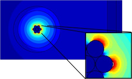
The example in Fig.6 is a 50kV vacuum feed-through where the central electrode is supported by a 100mm diameter ceramic disk. The front side is to be potted in silicone.
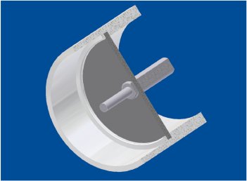
Fig. 7 shows a magnified cross-section view through the junction of the central pin and ceramic insulator. Here, the designer has recognized the need to avoid sharp edges and specified a radius on the turned shoulders.
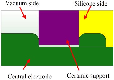
The electric field analysis in Fig.8 shows the field enhancement around the triple junction of the metal pin, the ceramic disk and the vacuum. In this case the electric field exceeds 20kV/mm (shown in red) and could damage the ceramic, ultimately leading to total breakdown.
"An interesting point is the tolerance gap between the pin and the ceramic," comments Ainsworth. "The electric field is 11kV/mm in this example and could easily cause a breakdown under certain circumstances. If, in a particular assembly, the gap were smaller, then the electric field would rise further. Although this is a stylized design, it does demonstrate the need for accurate and complete modeling."
3. Minimizing potting material: It is often assumed that increasing the thickness of insulation will improve the voltage rating of a particular design. Alternatively, where insulation has failed, the temptation can be to add more material. This approach is usually ineffective, unless the electric field has been modelled and the root cause clearly understood.
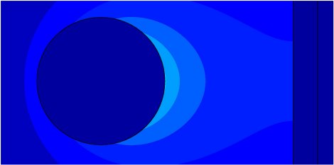
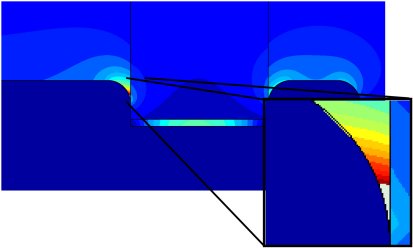
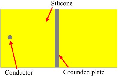
The example in Fig.9 shows a 40kV high voltage conductor of 1mm diameter encapsulated in silicone and located 10mm from a grounded plate. This is typical of electronic components used in voltage multipliers or dividers.
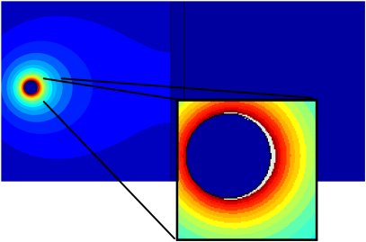
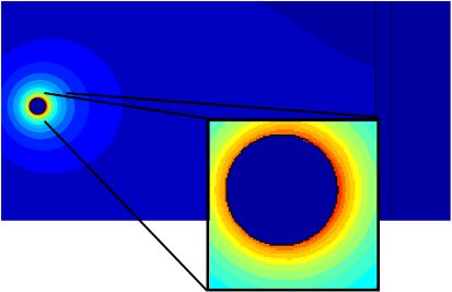
The analysis in Fig.10 shows a maximum electric field around the conductor of 21.9kV/mm. This is likely to result in a breakdown in the silicone. The effect of increasing the separation distance from 10mm to 20mm is shown in Fig.11. Here, the field has been reduced to 17kV/mm, a reduction of 22%, rather than the 50% which might have been expected.
Although the silicone may survive this electric field, in most cases it is beneficial to use shields to protect parts of the circuit from such stresses without the need for additional potting material.
Ainsworth concludes, "The use of electric field modeling software can be a very effective way of arriving at an optimum solution for a high voltage design. With electric field modeling, even quite subtle problems are easily identified, changes quickly made and further testing done. It is also vital that the software is easy to use, fast and presents its results clearly. When looking at modeling software to iterate your design, LORENTZ from INTEGRATED Engineering Software meets these requirements. It is far better to select packages with specific features, than generic packages which require further ‘programming’ before being used for simulation. INTEGRATED’s solution includes a CAD import facility, which is absolutely necessary, and it also allows one to quickly modify a design on-screen."
"For ease of use, calculations should be rapid and largely self-determining without the need to input any specific parameters such as meshing sizes etc. I would recommend that attention is paid to all aspects of the design, including such apparently benign components as screws and solder joints. Particular attention should be given to tolerances and fits of conductive and nonconductive materials."
"In most cases the electric field can easily be reduced by shielding or appropriate modifications. With experience, designers will become more familiar with good practice and in time, through this process, the number of design iterations will reduce and better ‘rules of thumb’ will be established."
"I believe that appropriately trained and informed mechanical designers often have the best insight into optimizing the layout of the high voltage components and quickly become familiar with the requirements. However, close collaboration with electronic designers is a vital part of the process and modeling software will speed up the time to market."
About Steve Ainsworth
Steve Ainsworth is the founder of Dart Research which is a start-up company based in Dartmouth, Devon, UK. The company is currently developing new products for high-value niche markets in x-ray inspection. Previously Ainsworth spent 15 years at Dage, now part of the Nordson group. As Director of Engineering he was involved in the development of award winning innovative products. Establishing Dart Research is his next challenge.
For more information, contact us here
A Trustworthy Simulation Tool: designing switches and insulation systems in high voltage systems
Paul Stoving, Senior Design Engineer at Cooper Power Systems, explains how and why INTEGRATED’s oldest customer is still using ELECTRO, 22 years after they first purchased it.
Paul Stoving is the Senior Design Engineer in the Vacuum and High Voltage Engineering Department at Cooper Power Systems, headquartered in
A Trustworthy Simulation Tool: designing switches and insulation systems in high voltage systems
Cooper Power Systems case study
Cooper Power Systems, headquartered in Waukesha, Wisconsin, manufactures a variety of high voltage and high current products such as switches, insulators and other electrical components. The company first began using software from INTEGRATED Engineering Software in 1987, which makes Cooper Power INTEGRATED’s oldest current customer. In recognition of Cooper Power Systems’ loyalty, INTEGRATED has made a donation to the United Way of Milwaukee in their name.
Paul Stoving, Senior Design Engineer at Cooper Power Systems, explains how and why INTEGRATED’s oldest customer is still using ELECTRO, 22 years after they first purchased it.
Paul Stoving is the Senior Design Engineer in the Vacuum and High Voltage Engineering Department at Cooper Power Systems, headquartered in Waukesha, Wisconsin. The company manufactures a variety of high voltage and high current products such as switches, insulators and other electrical components.
Cooper Power Systems initially purchased ELECTRO and MAGNETO back in 1987 to design field shaping of switches. Interestingly, the software they purchased 22 years ago is being used for the same thing today as it was back then.
Stoving’s department specifically designs high voltage, high current switches. He explains, "If you think about the circuit breakers in your house, they are probably a few amps and 120 volts. We design circuit breakers for power lines where they interrupt up to 16,000 amps and anywhere from 15 to 38,000 volts. My department is responsible for designing the switches and the insulation".
This department uses ELECTRO extensively as one of their main software packages. ELECTRO is mainly used for shaping the electric field in and around circuit breakers. They occasionally use Magneto as well. Magneto is used for designing solenoids, magnetic actuators and other parts that open and close the switches. Since they first bought INTEGRATED’s software, they use it so extensively that a few years ago they required another pair of licenses.
Why is the company still using ELECTRO after so many years and not other packages available on the market? "Two main drivers for that" answers Stoving, "ease of use when going through a lot of conceptual designs trying different iterations for building up and altering models, and for importing models in from CAD."
Stoving continues: "The Boundary Element Method in INTEGRATED’s software, especially ELECTRO, is incredibly easy to use. It’s very easy to build the model and does not require a lot of effort to apply the mesh to get a meaningful model. It’s easy to move components around and change the model. Using a FEA package a lot of times means you’ll have to start building the model again from the bottom up, where in ELECTRO you just create the component and adjust it. That’s pretty much all you have to worry about."
Stoving is not a "big fan" of automatic meshing in FEA because he finds it tends to give poor results, but talking about ELECTRO he states: "I have a good degree of confidence in the automatic meshing that ELECTRO uses: it’s very reproducible and very reliable, as the method of refinement is based on a solid error criteria. The really nice feature here is that I can adjust the error criterion for the automatic refinement, so if I need a quick answer, I can solve one way, and if I need a reliable answer, I can set it another, and that, as said, the refinement is based on the error calculation." And he adds, "ELECTRO is pretty much the only program I trust self adaptive and automatic meshing with. If I am building a model in other CAE software, I will be pretty much doing everything manually and going through it manually; I am not a big fan of automatic meshing with FEA software because it always seems to produce poor meshing results right into the area you are interested in. But ELECTRO does a very good job of it. I’d prefer an aggressive mesher that throws a lot of elements at a problem versus an automatic mesher that oversimplifies the problem and yields questionable results."
In terms of technical support, Stoving observes that he has been using the software enough that he doesn’t have to call for "help" but he certainly is not afraid to call if he encounters a bug. He appreciates that the solutions may result in adding a new feature to the tool.
"It’s always been a pleasure dealing with INTEGRATED." Stoving finalizes, "My intention is to continue using their software for a long time. Unlike their competitors, who will fix a problem in their next new release, which may come in a year, INTEGRATED has always been very receptive; they have a very fast turnaround with any sort of issue. The fact is that they’ll recompile a specific release of the software just as a result of a bug and usually within a week. They come back with the new version of the software that has corrected the bug, and that’s just remarkable."
For more information, contact us here
Simulation software analyzes magnetic flux density near distribution power lines
IREQ takes full advantage of the Boundary Element Method field solver for the analysis of its open region problems
Hydro-Québec is a power utility owned by the province of Quebec. Hydro-Québec’s Research Institute (IREQ) is the research arm of Hydro-Québec and one of North America's leading research and testing centers for the study of electrical power generation, transmission and distribution...
Simulation software analyzes magnetic flux density near distribution power lines
Hydro-Québec Research Institute (IREQ) case study
IREQ takes full advantage of the Boundary Element Method field solver for the analysis of its open region problems
By Sylvain Gravel
Senior research scientist
Hydro-Québec Research Institute (IREQ)
Hydro-Québec is a power utility owned by the province of Quebec. Hydro-Québec’s Research Institute (IREQ) is the research arm of Hydro-Québec and one of North America's leading research and testing centers for the study of electrical power generation, transmission and distribution.
Anywhere electric power is created, electric and magnetic fields are produced. At lower voltages and currents the fields produced are normally of little concern. However, at high voltage or current levels the distribution of the electrical and magnetic fields must be carefully taken into account to improve equipment reliability and protect the public and the workers.
Sylvain Gravel is a senior researcher at IREQ. His team analyzed the magnetic flux density near a complex configuration of distribution power lines. As this class of problems exhibits no symmetry, a full 3D analysis model was required.
To solve these complicated magnetic structures, two completely different approaches can be used. One is formulating Maxwell’s equations in differential form and the other is in integral form. The first is associated with Finite Elements and the second with Boundary Elements. Being an open region problem, it can be best analyzed through the Boundary Element Method (BEM) instead of Finite Element Method since it avoids the need of creating a mesh in an open space, even far from the area to analyze.
Gravel comments, "BEM software solves Maxwell’s equations in integral form using an equivalent source Green’s function approach so computational elements need only to be defined on the surfaces of interest and not inside of them."
By using FARADAY, an easy-to-use 3D eddy current solver created by INTEGRATED Engineering Software, IREQ is able to analyze the magnetic flux density values in 3D. IREQ has been using INTEGRATED’s software since 1985 and FARADAY in particular since 1999.
"FARADAY is ideally matched to the power line problems" Gravel explains, "This is one of the best applications we’ve had with FARADAY, it is very well suited for analyzing power lines because it deals with open boundary problems. We’ve arrived to very good results through this software."
FARADAY computes the fields from the given distributed currents. Once a volume to analyze is defined and the field values computed, the isosurfaces of equal magnetic flux density can be plotted revealing their shape, exact position and extent in space in relation to the conductors.
For many open region problems the number of unknowns required by Finite Element techniques would become prohibitive. INTEGRATED Engineering Software offers both Finite Elements and Boundary Elements enabling the user to select the right technology for a given problem.
By using FARADAY in conjunction with an easy to use graphical interface, IREQ can readily view resultant magnetic fields. In addition, the geometry can be varied parametrically to obtain an optimal magnetic field configuration.
Gravel closes: "INTEGRATED offers us the right tools for analyzing open boundary problems, and we are very satisfied with FARADAY for these applications."
Note: The figures below were created with Tecplot 360 (Tecplot Inc.).
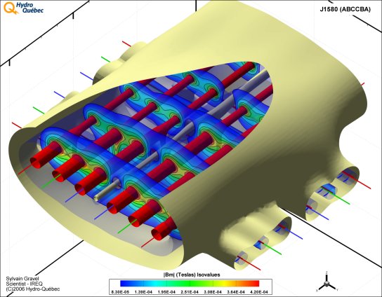
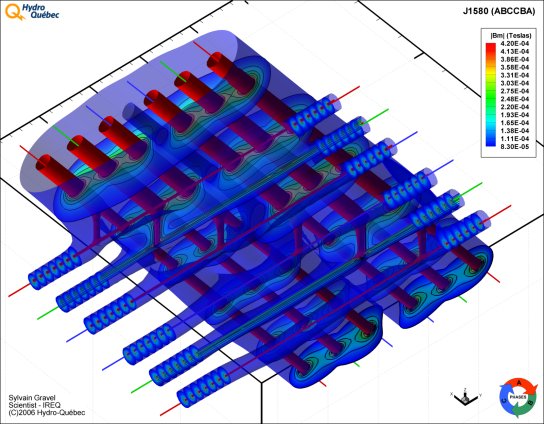
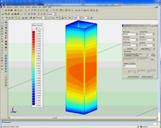
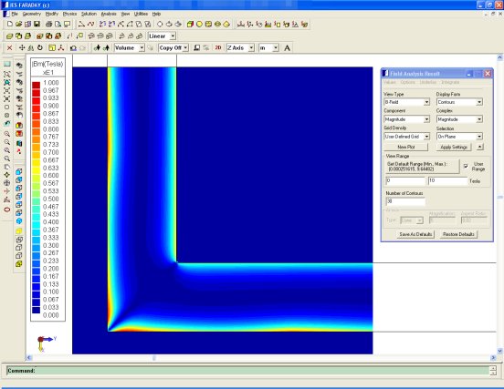
For more information, contact us here